This install guide will show you how to install a pause button switch inside the Sega Master System controller and a logic circuit inside the console that allows the switch to work. Mods using Mega Drive and NES controllers exist, but this pause button mod is designed to retain the use of original controllers whilst having the benefit of a pause button.
Solder Maps
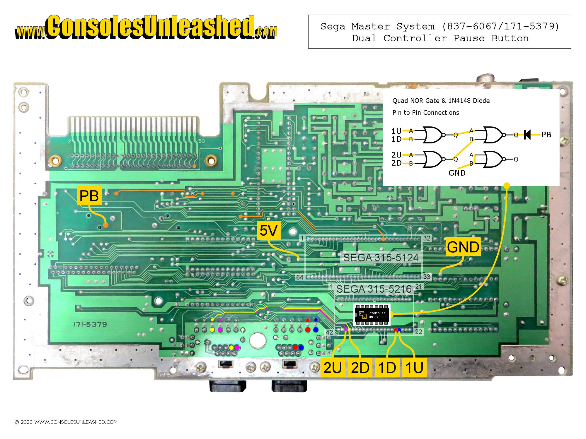
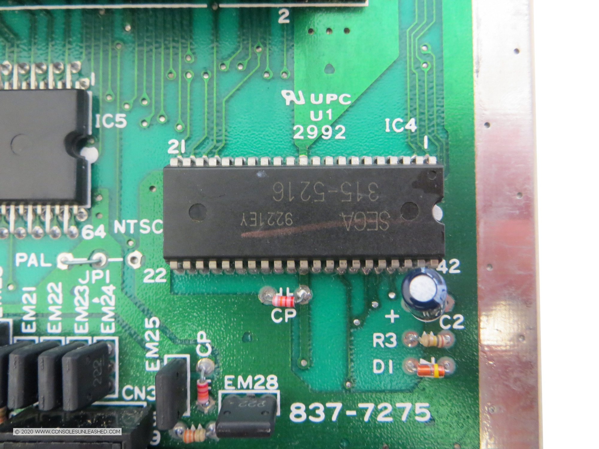
Sega Master System – NTSC-U / 837-6067 / 171-5379
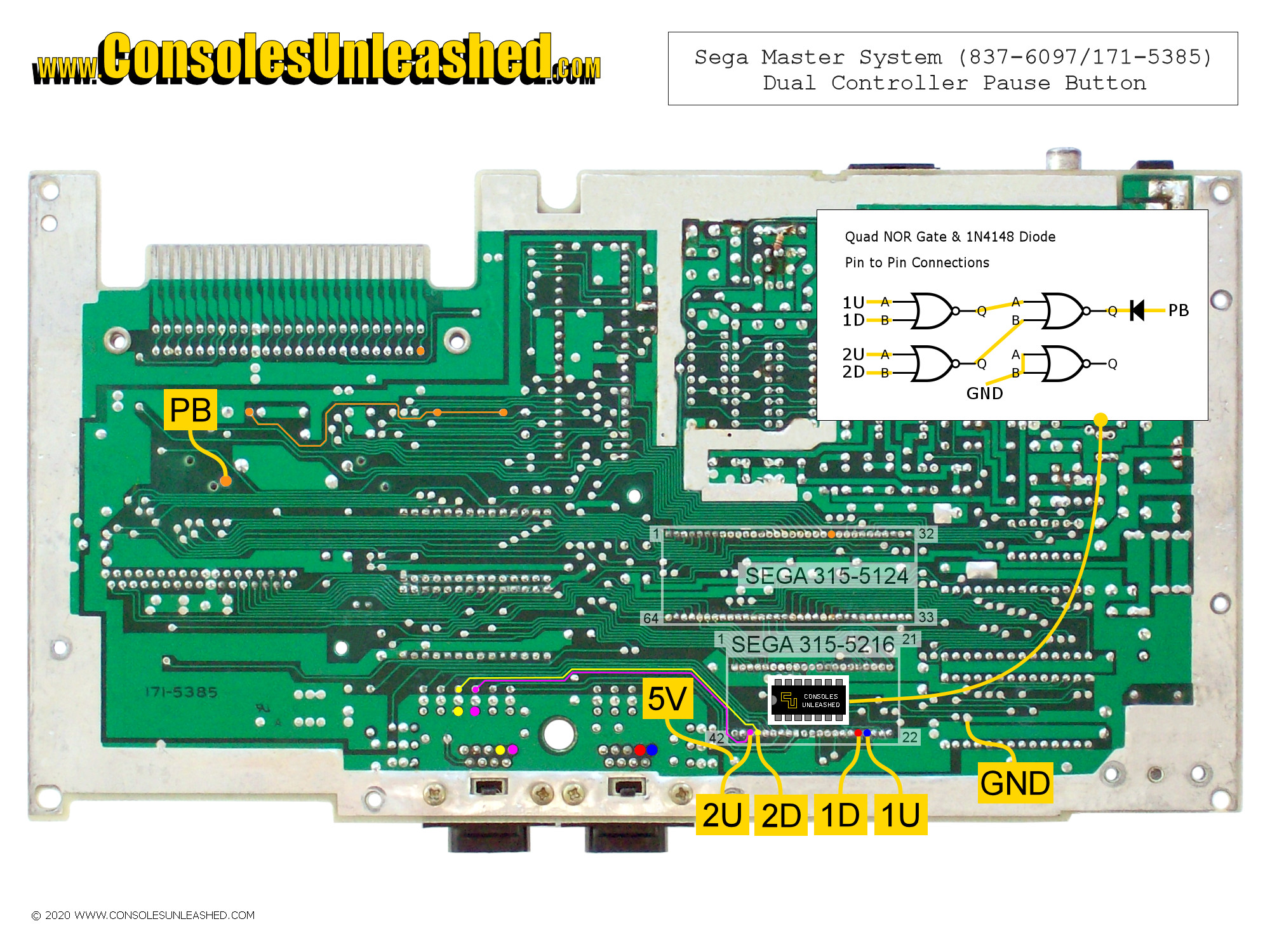
Sega Master System – PAL / 837-6097 / 171-5385
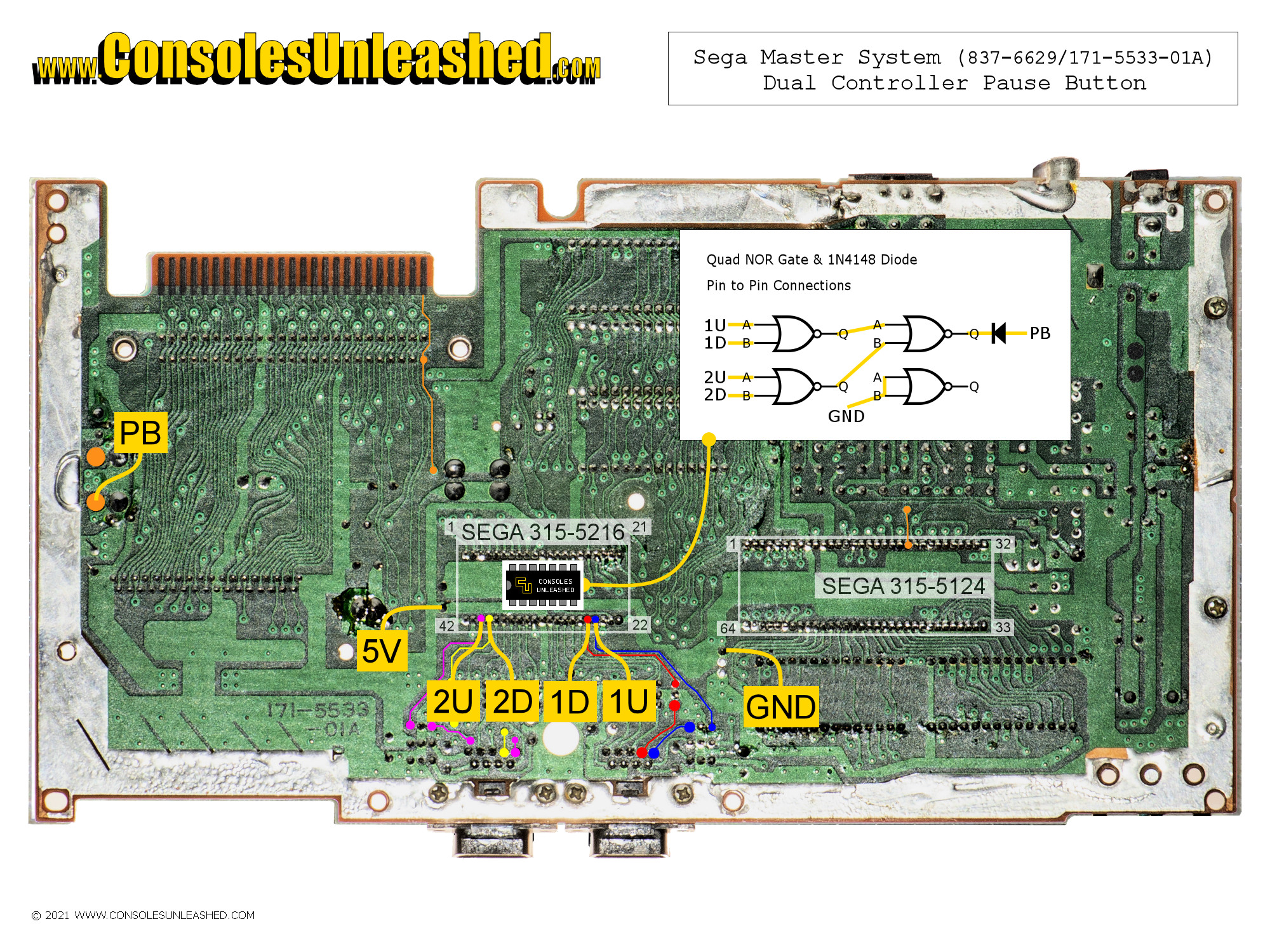
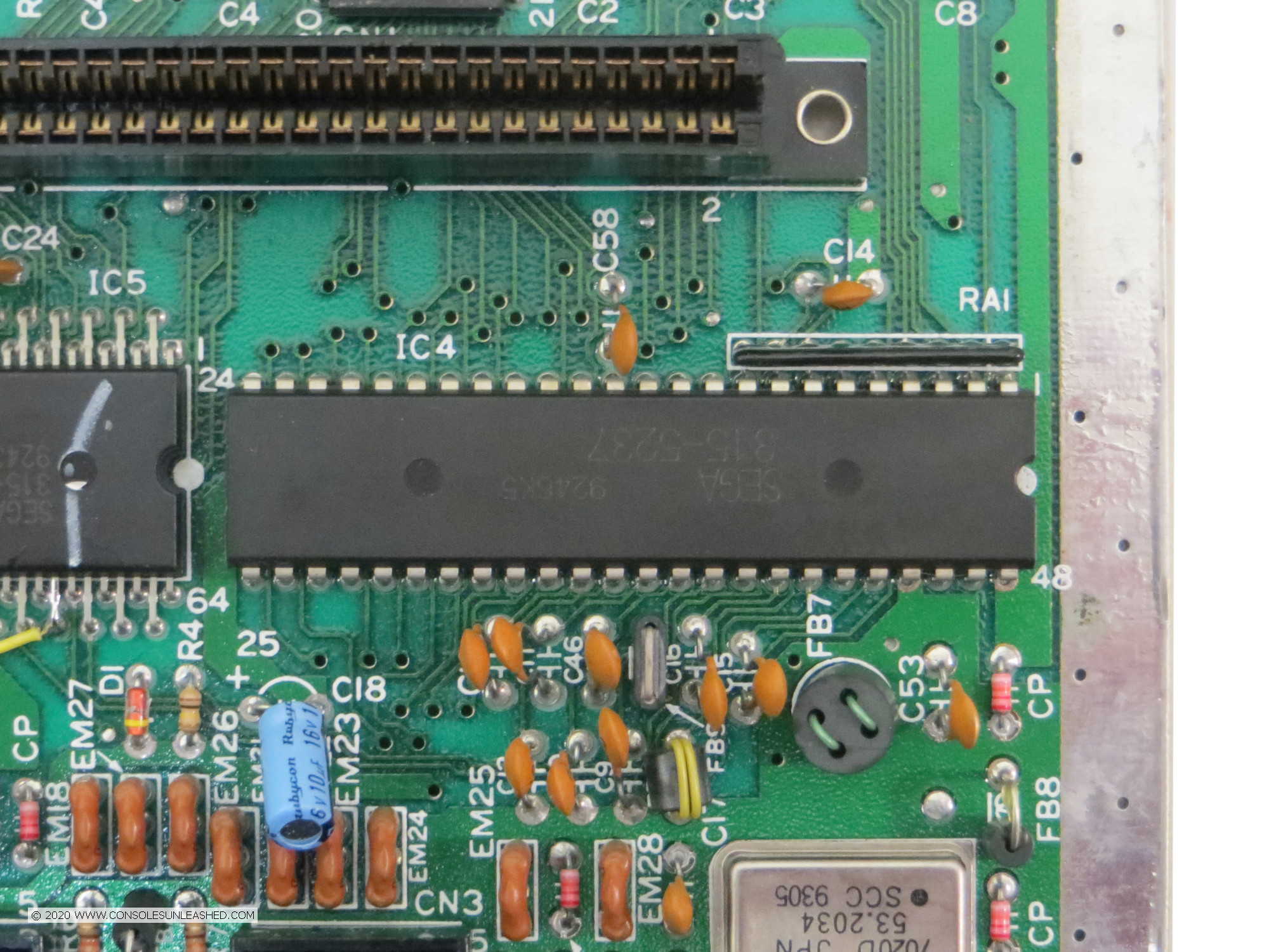
Sega Master System – NTSC-U / 837-6629 / 171-5533-01A
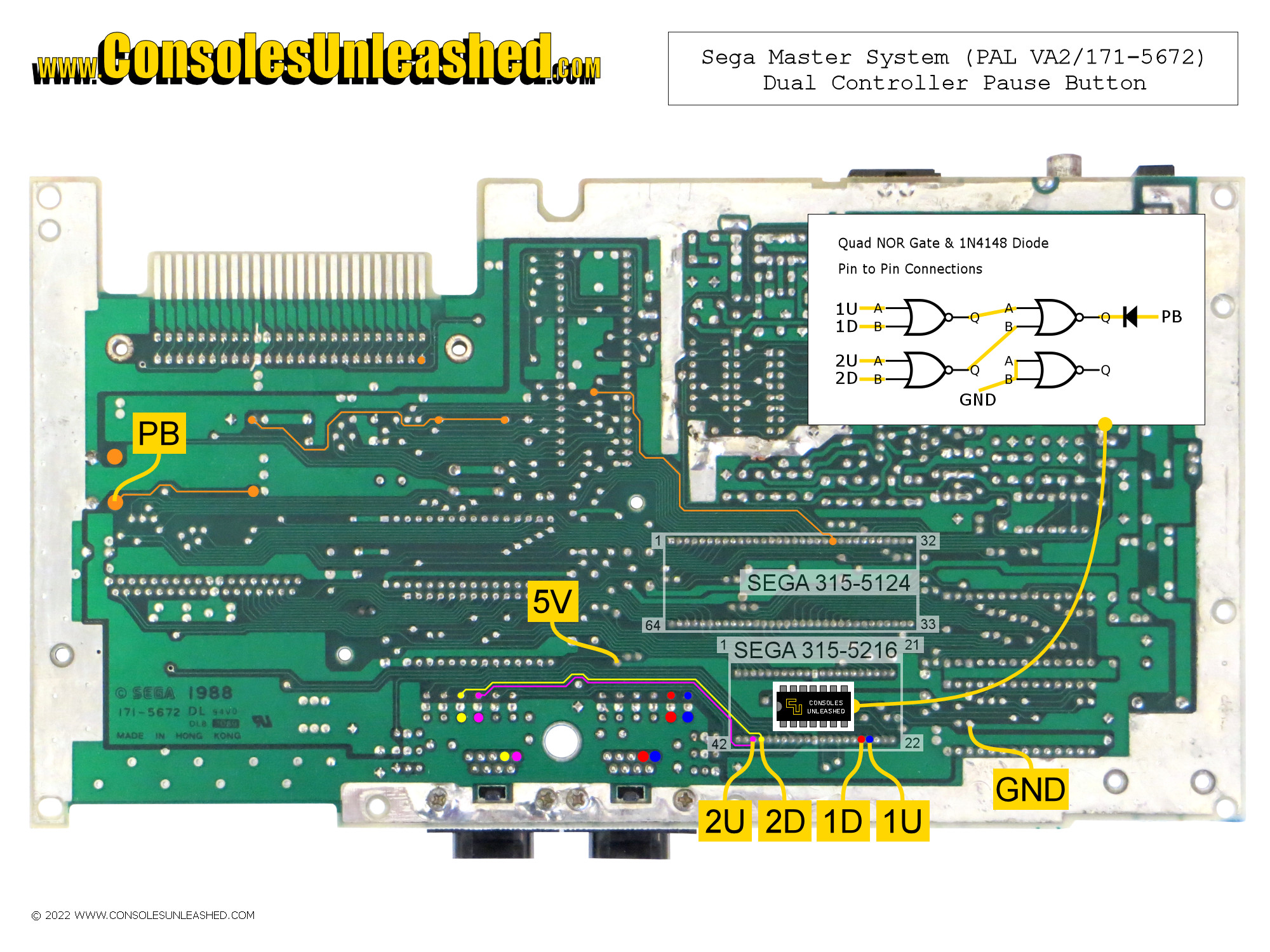
Sega Master System – PAL / VA2 / 171-5672
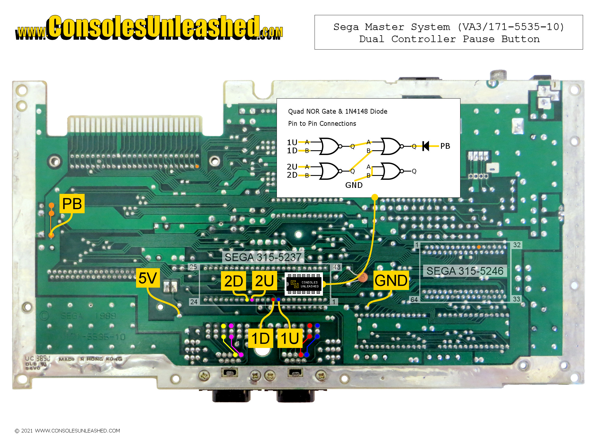
Sega Master System – PAL / VA3 / 171-5535-10
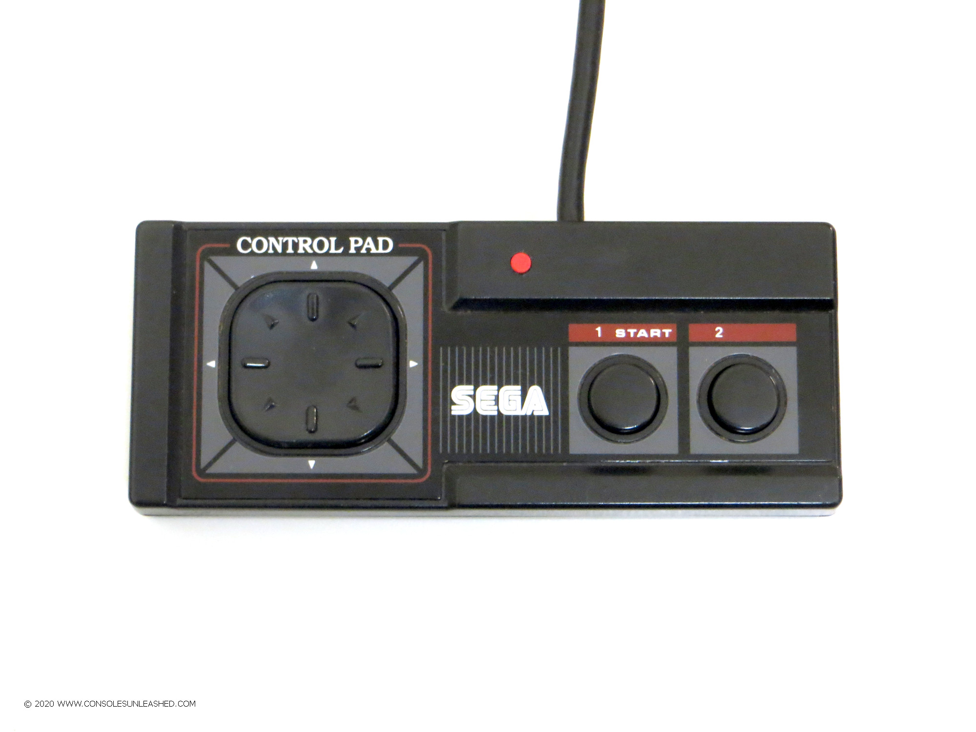
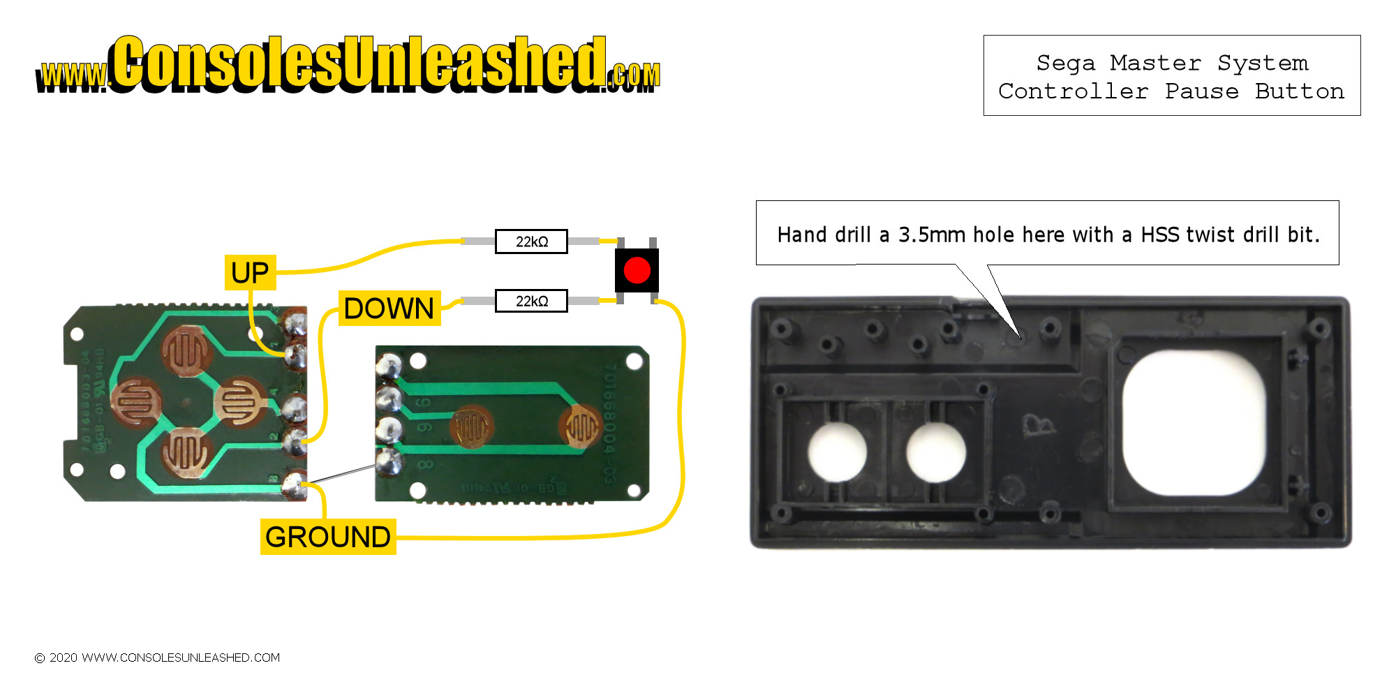
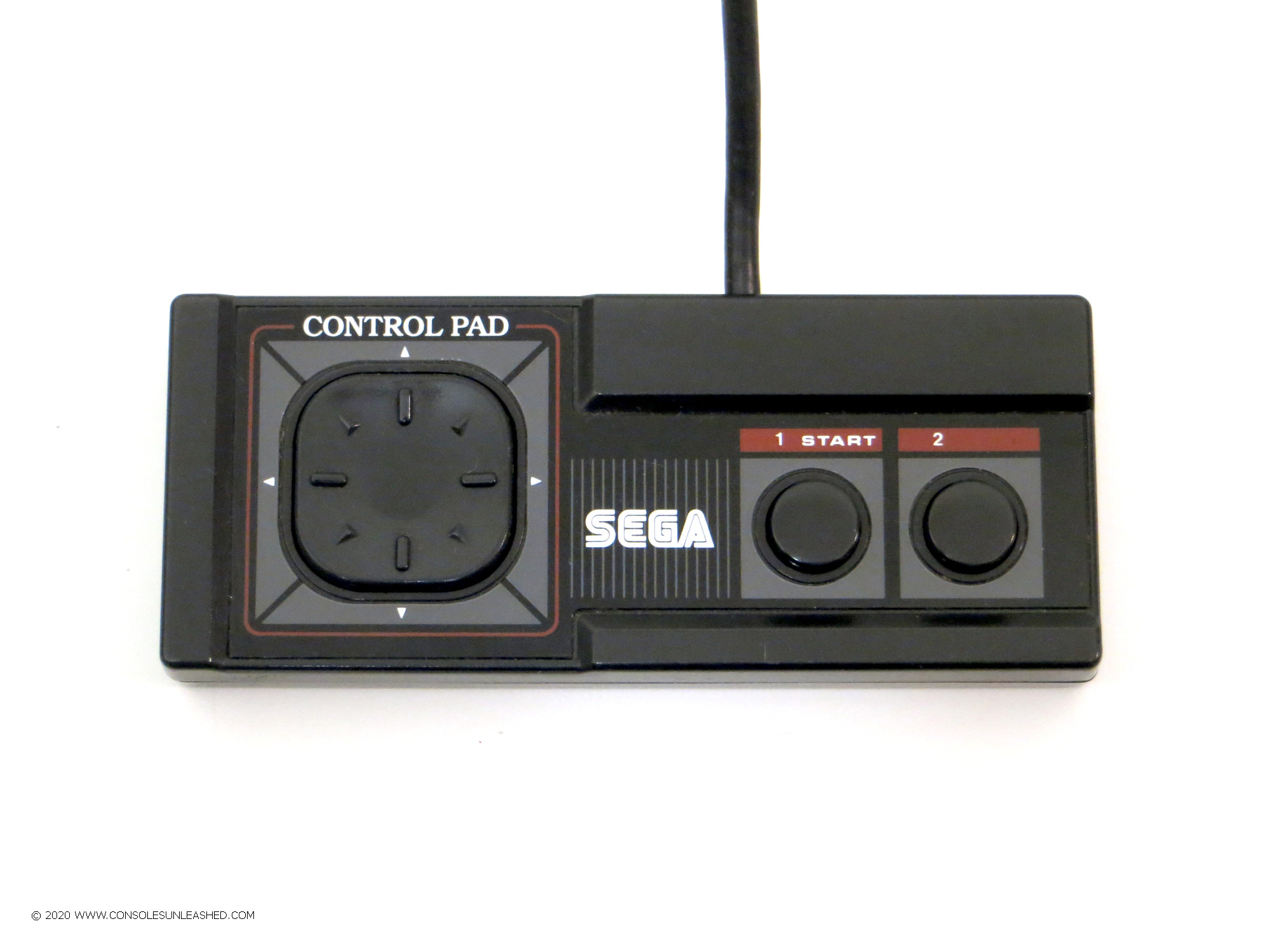
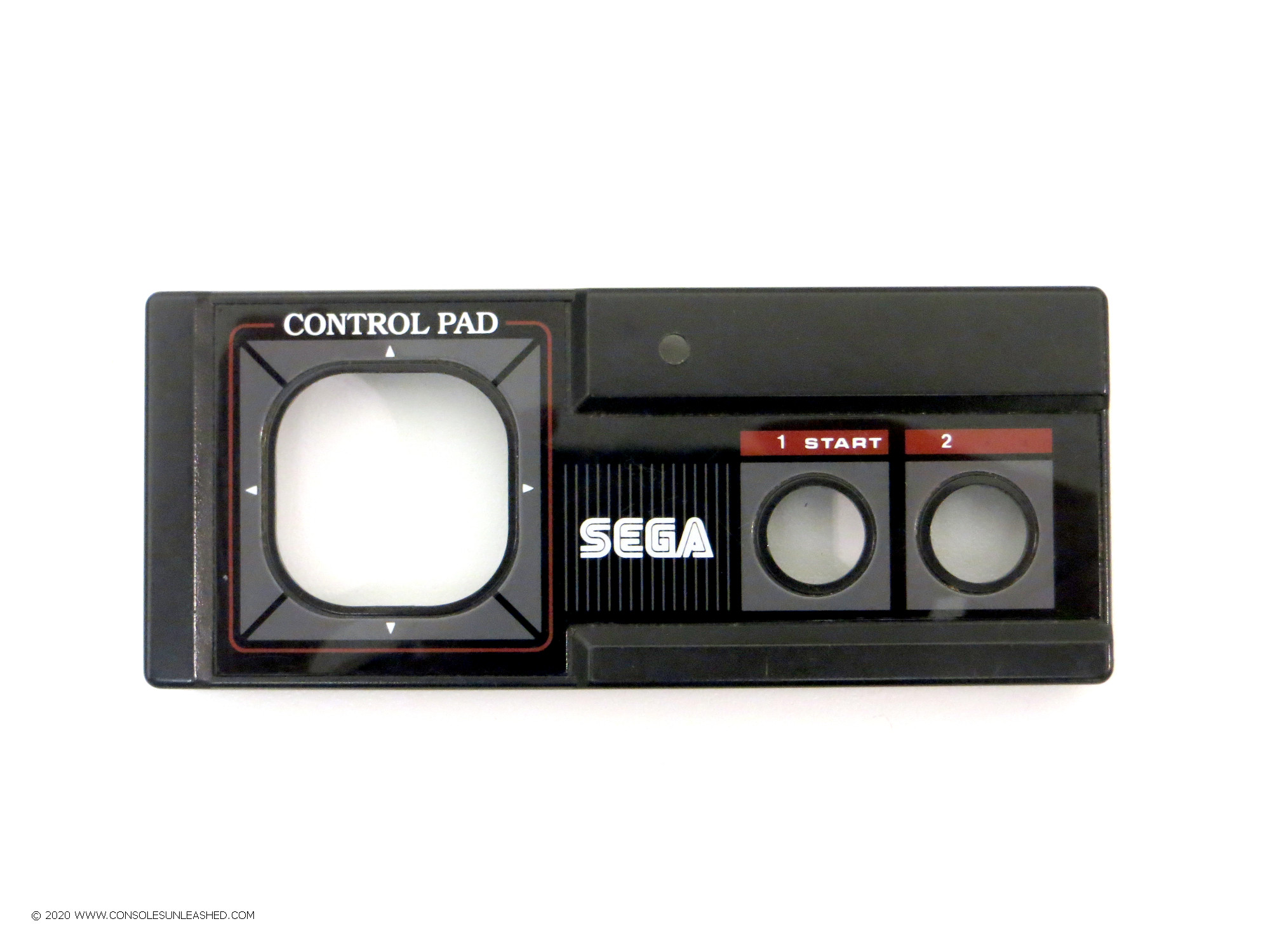
Sega Master System Controller
Logic
OR Gate
To have pause on one controller.
| OR Gate | ||||
| IN | OUT | |||
| Pause Button (Z) | 1A | 1B | 1Q | |
| Controller 1 | 1 (Default) | 1 | 1 | 1 |
| Controller 1 | 0 (Pressed) | 0 | 0 | 0 |
Quad NOR Gate
To have pause on two separate controllers that work independently.
| NOR Gate 1 | NOR Gate 2 | Outputs 1Q and 2Q feed inputs 3A and 3B. | NOR Gate 3 | ||||||||
| IN | OUT | IN | OUT | IN | OUT | ||||||
| Pause Button (Z) | 1A | 1B | 1Q | 2A | 2B | 2Q | 3A | 3B | 3Q | ||
| Controller 1 | 1 (Default) | 1 | 1 | 0 | 0 | 1 | |||||
| Controller 2 | 1 (Default) | 1 | 1 | 0 | 0 | ||||||
| Controller 1 | 0 (Pressed) | 0 | 0 | 1 | 1 | 0 | |||||
| Controller 2 | 1 (Default) | 1 | 1 | 0 | 0 | ||||||
| Controller 1 | 1 (Default) | 1 | 1 | 0 | 0 | 0 | |||||
| Controller 2 | 0 (Pressed) | 0 | 0 | 1 | 1 | ||||||
| Controller 1 | 0 (Pressed) | 0 | 0 | 1 | 1 | 0 | |||||
| Controller 2 | 0 (Pressed) | 0 | 0 | 1 | 1 | ||||||
Step-by-Step Install Guide
This guide will show you how to install Consoles Unleashed Quick Solder Pause mod kits.
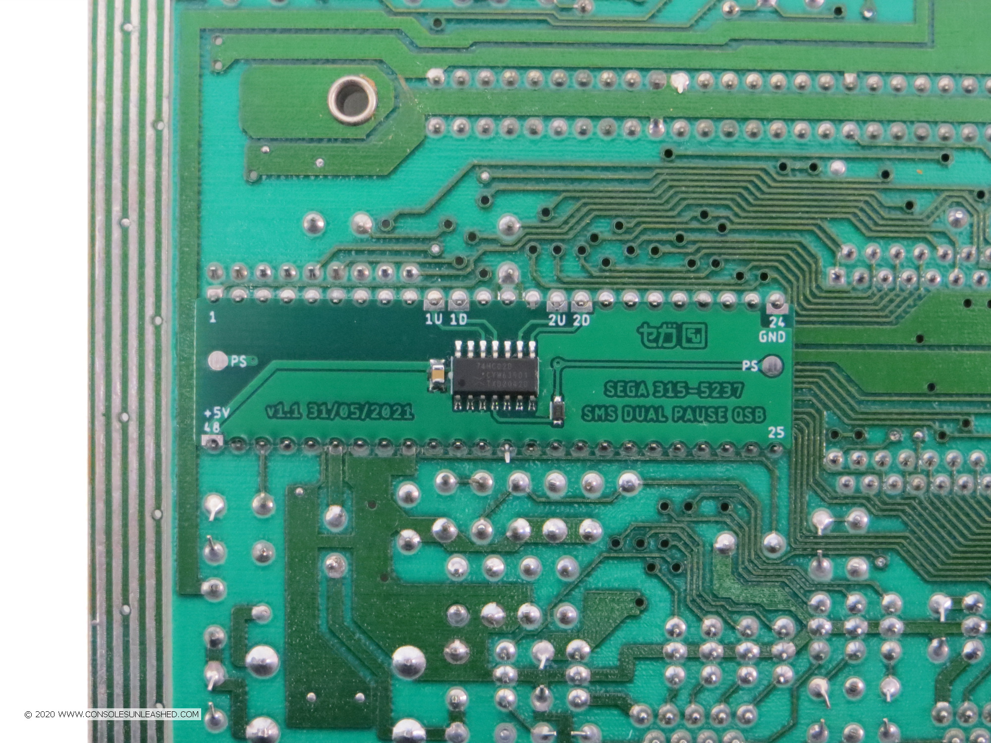
Sega Master System Pause Mod Logic Board
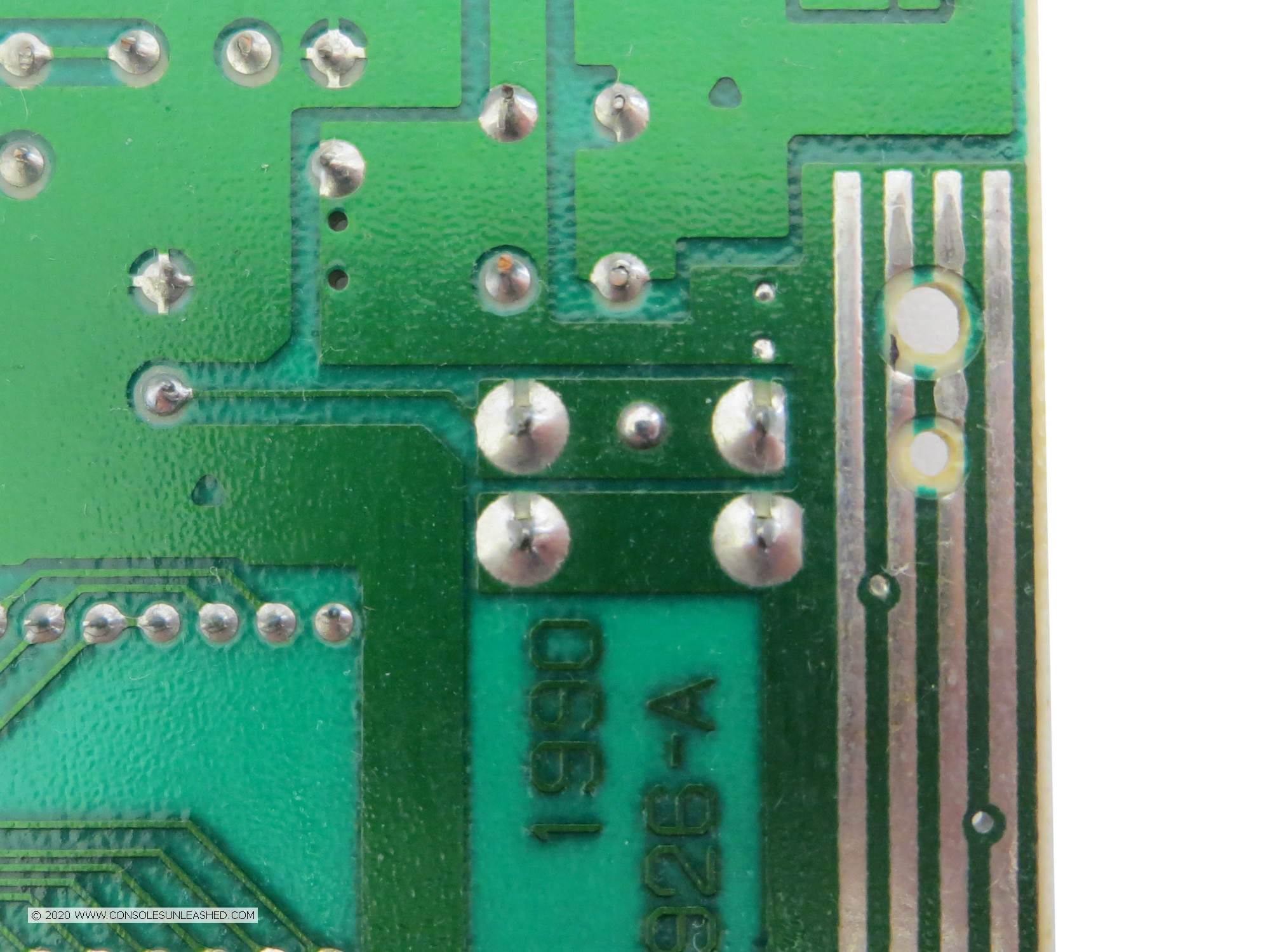
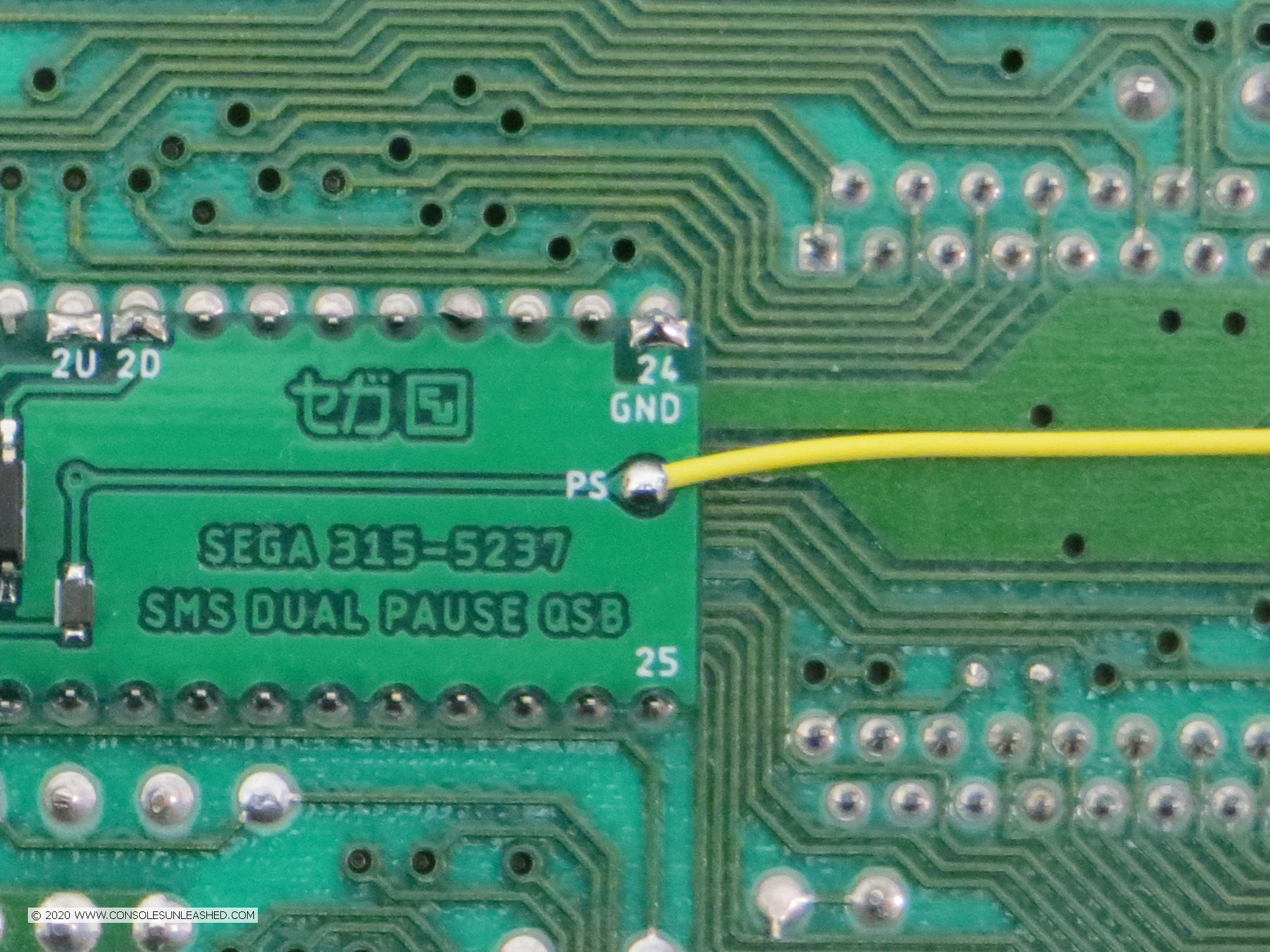
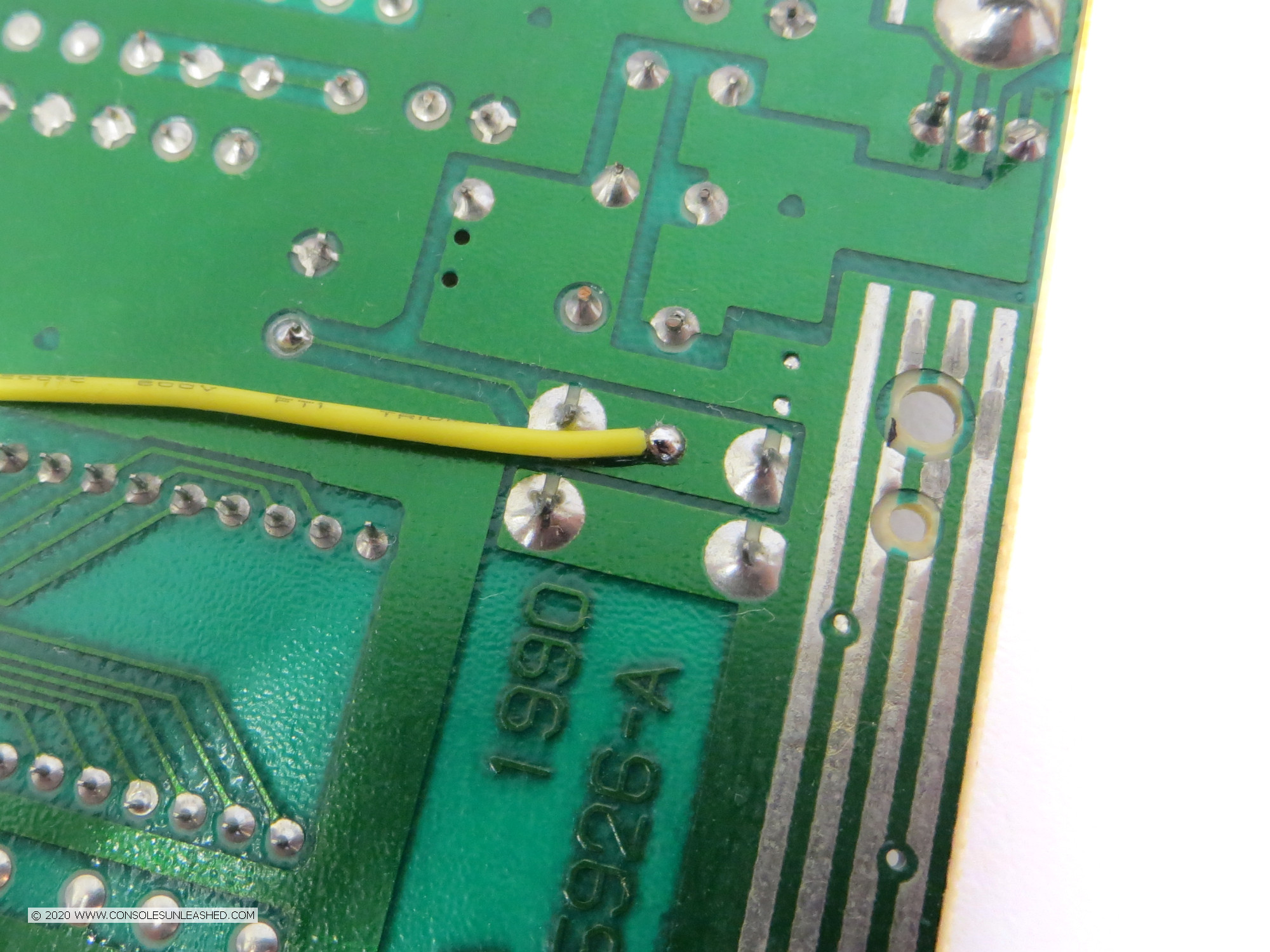
The logic board is the part that is installed into the console. There are three types available. Standard/universal full wire kit, SEGA 315-5237 QSB, and SEGA 315-5216 QSB. The standard version will need wiring to all the points shown in the solder map. The QSB versions need wiring to only the PB solder point.
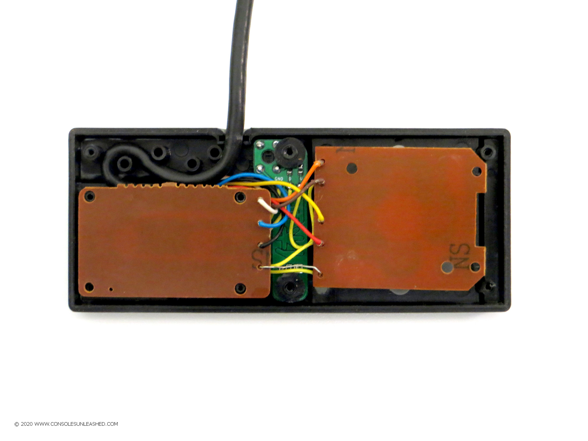
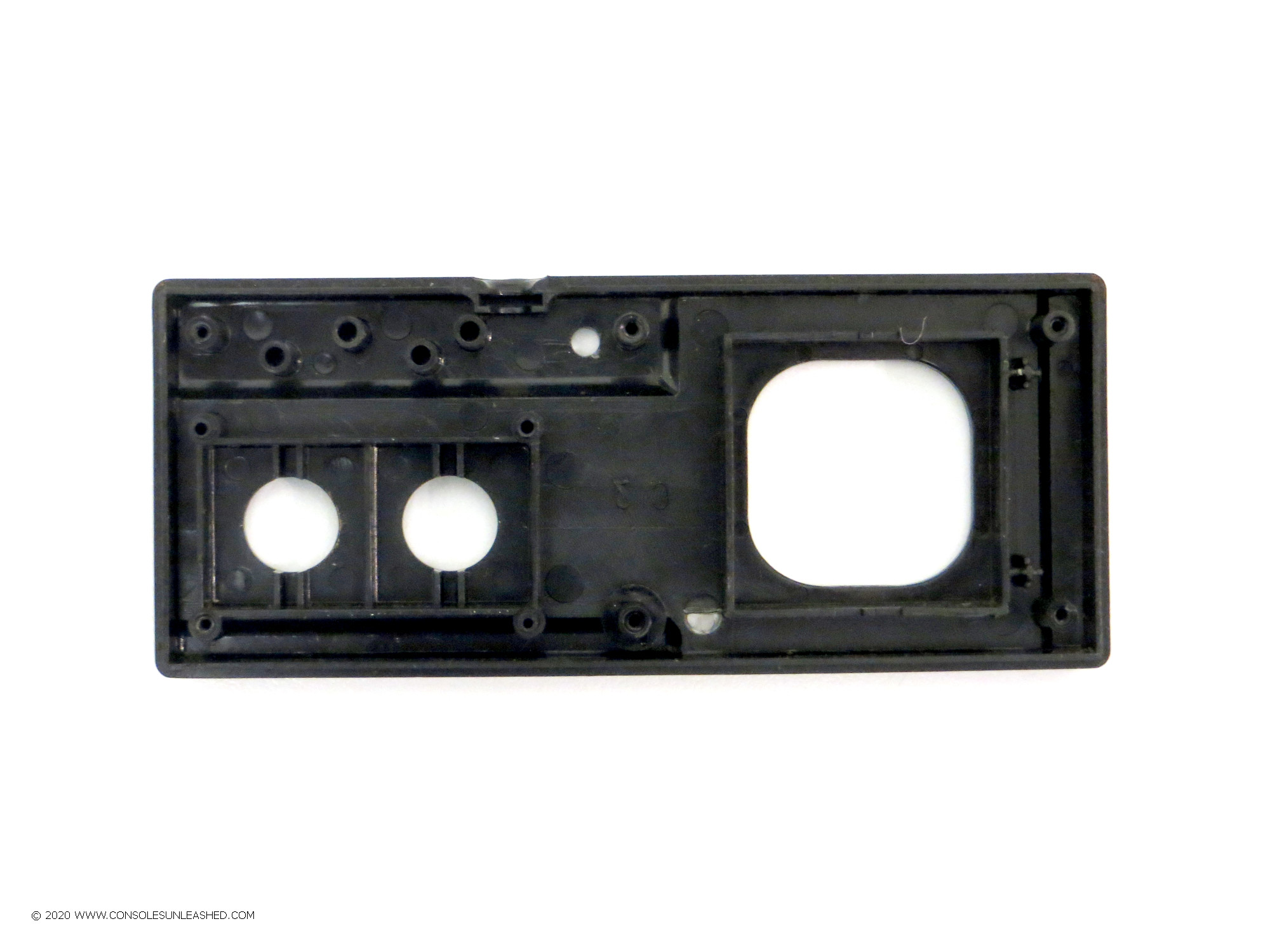
Sega Master System Controller Pause Button
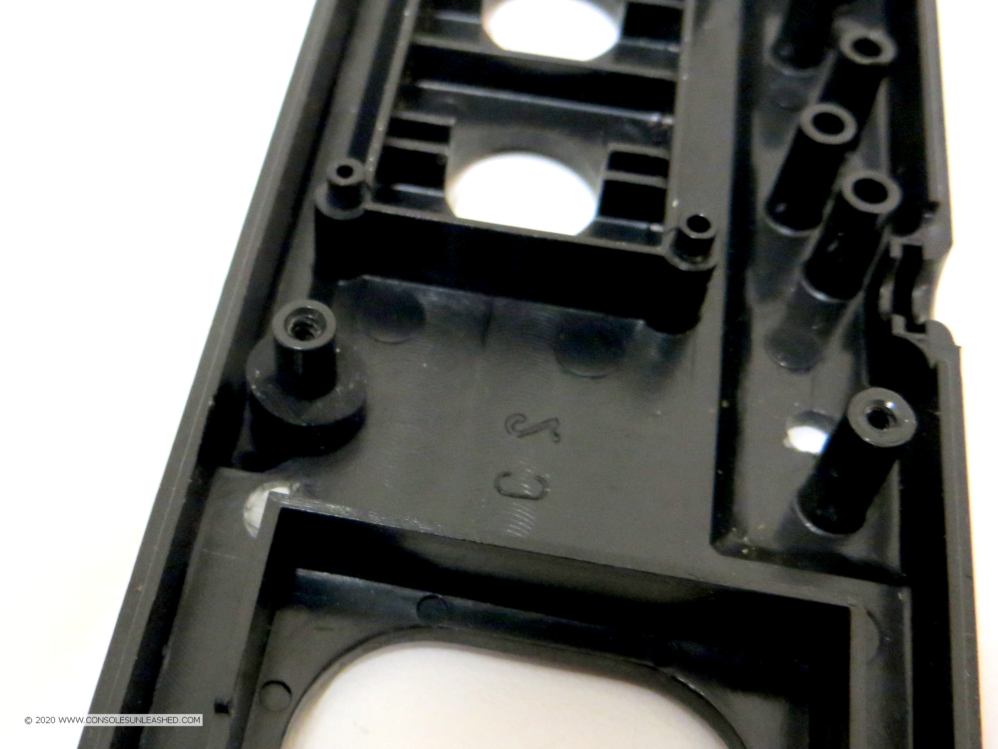
1 – Open the controller and remove all the parts from the top part of the shell.
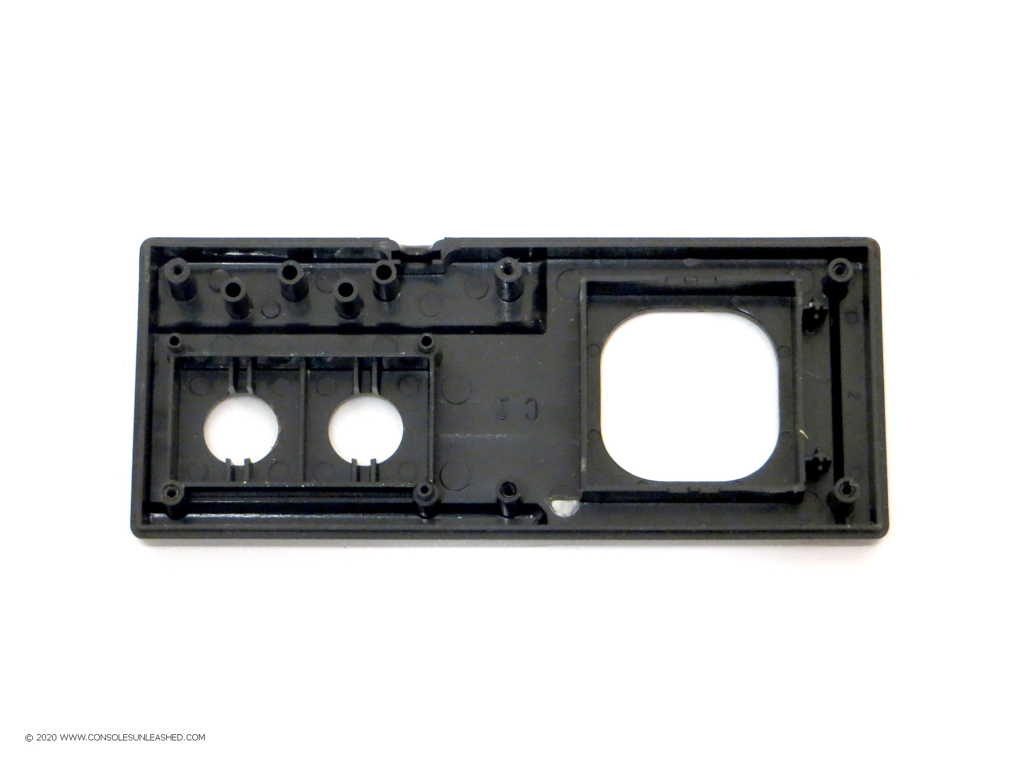
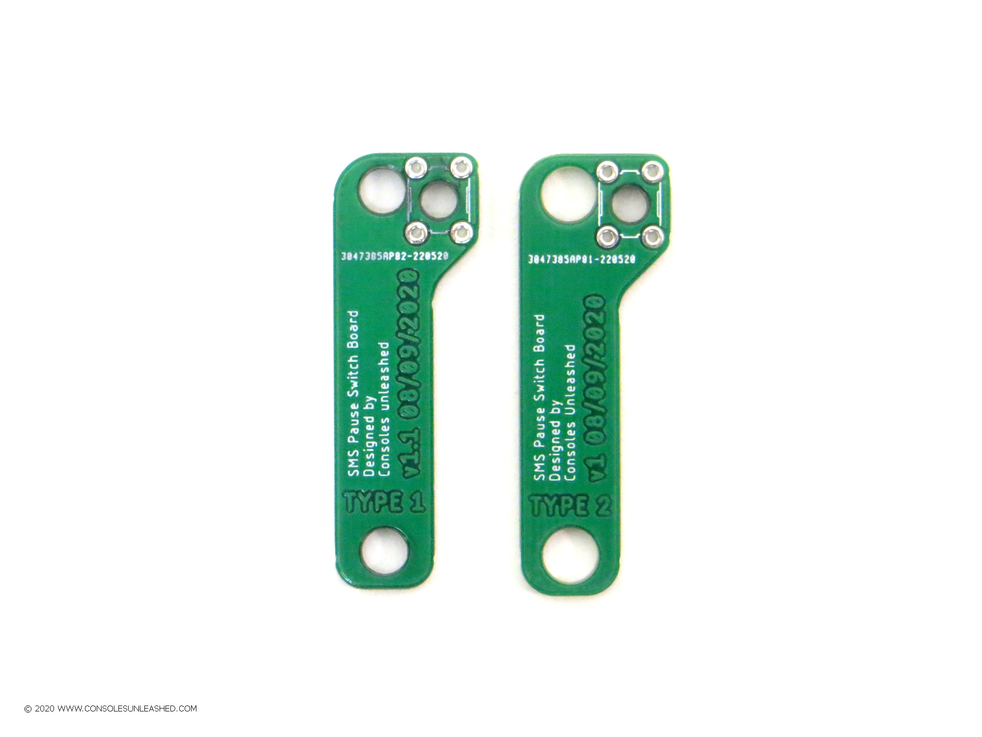
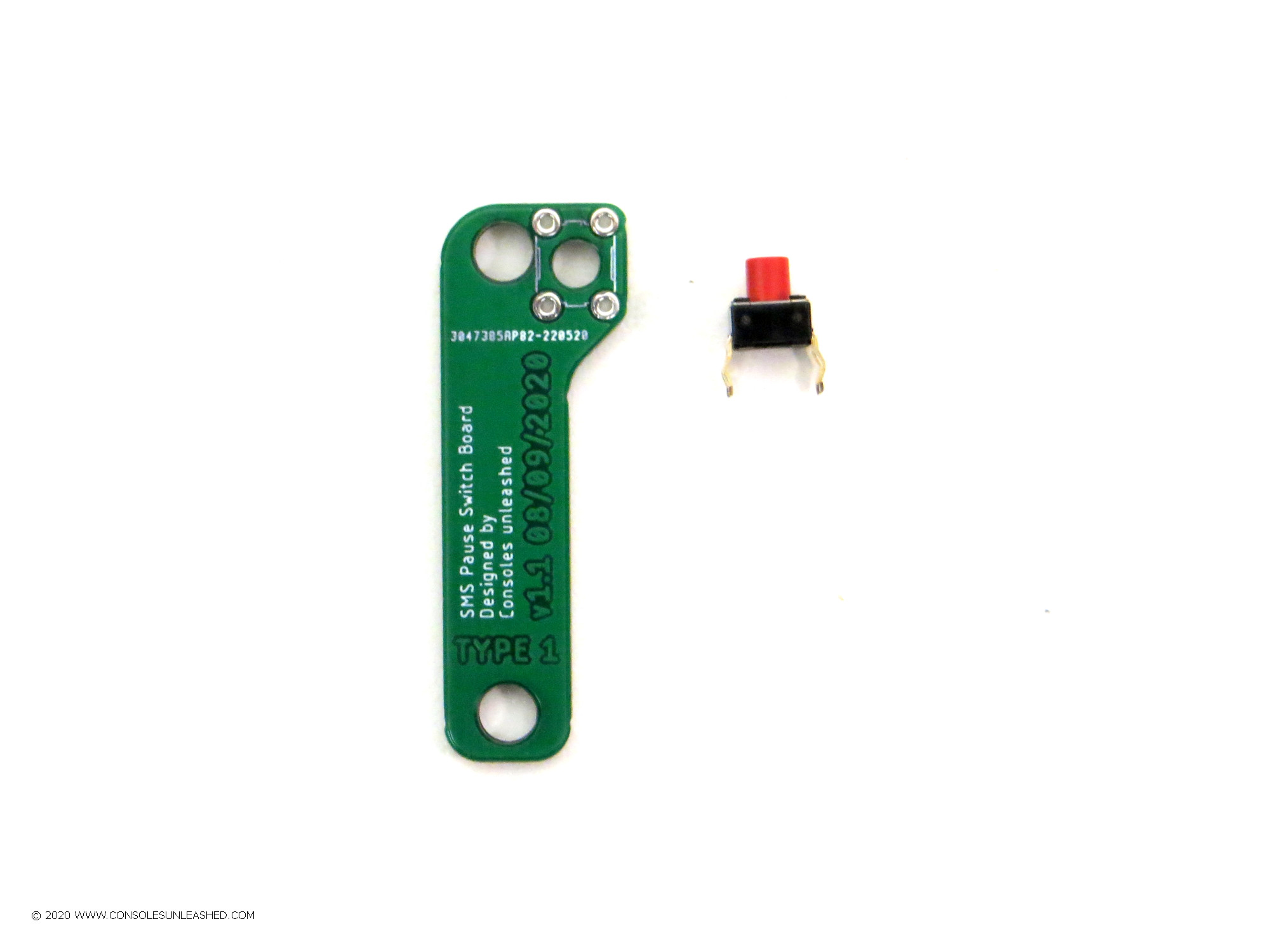
2 – There are two types of switch board. Type 1 and Type 2. They both have different size holes to fit different size pegs in the Master System controller. If Type 1 does not fit, use Type 2.
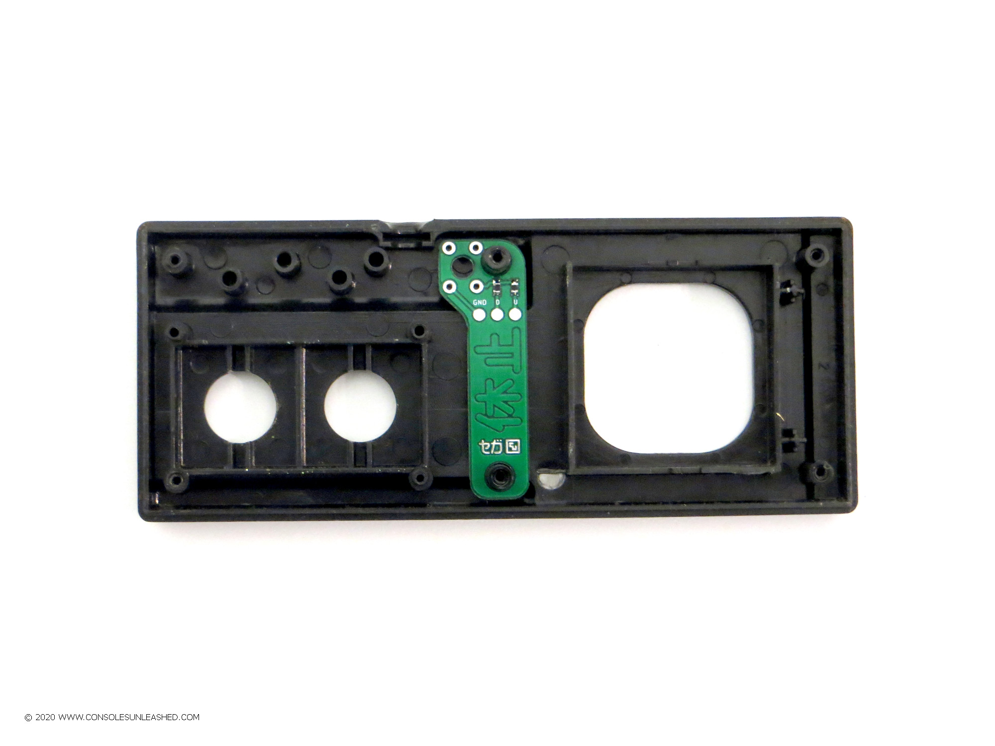
3 – Place the switch board over the two pegs. Do not install the switch into the switch board as it needs to be used as a drill template first.
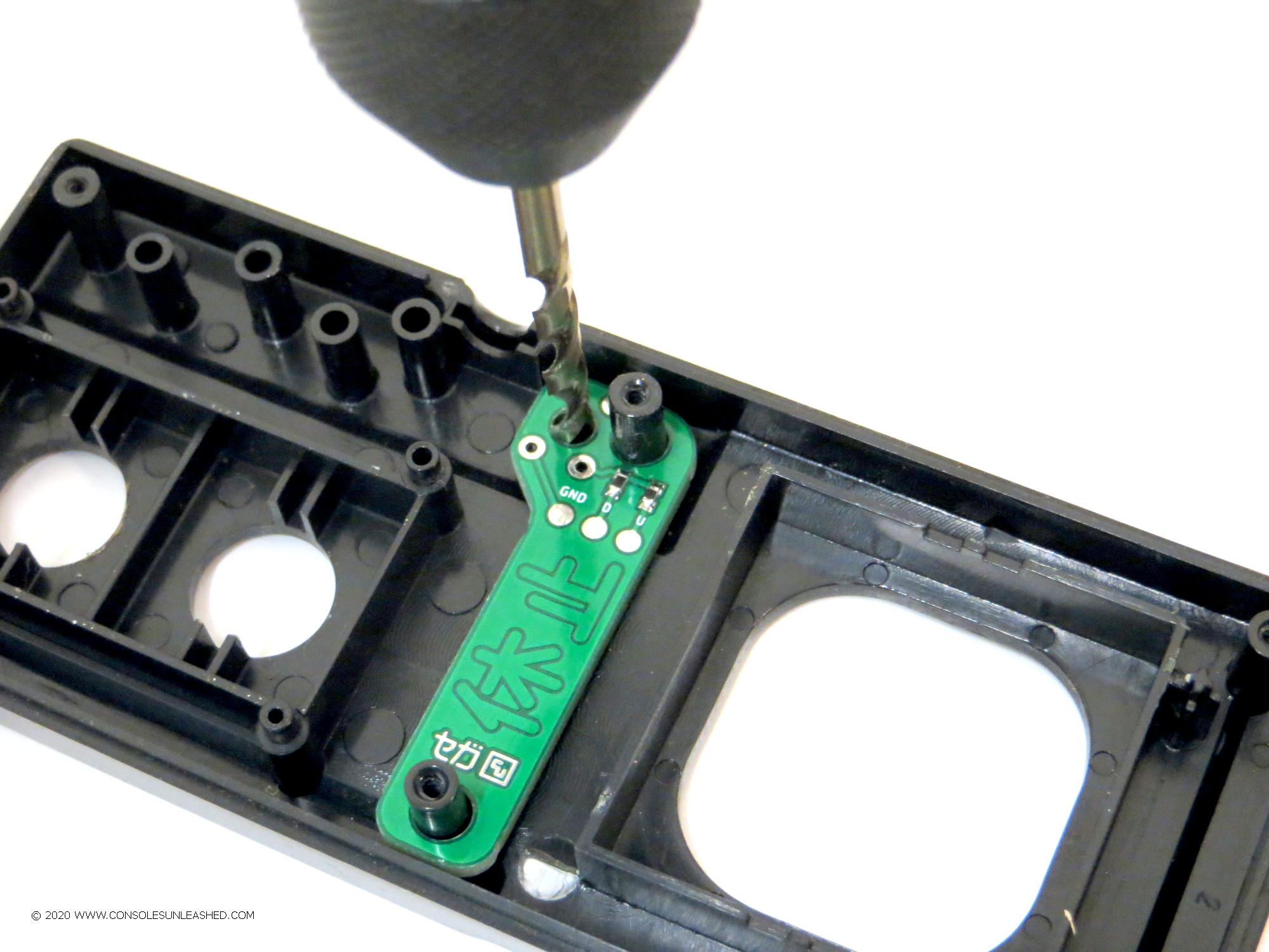
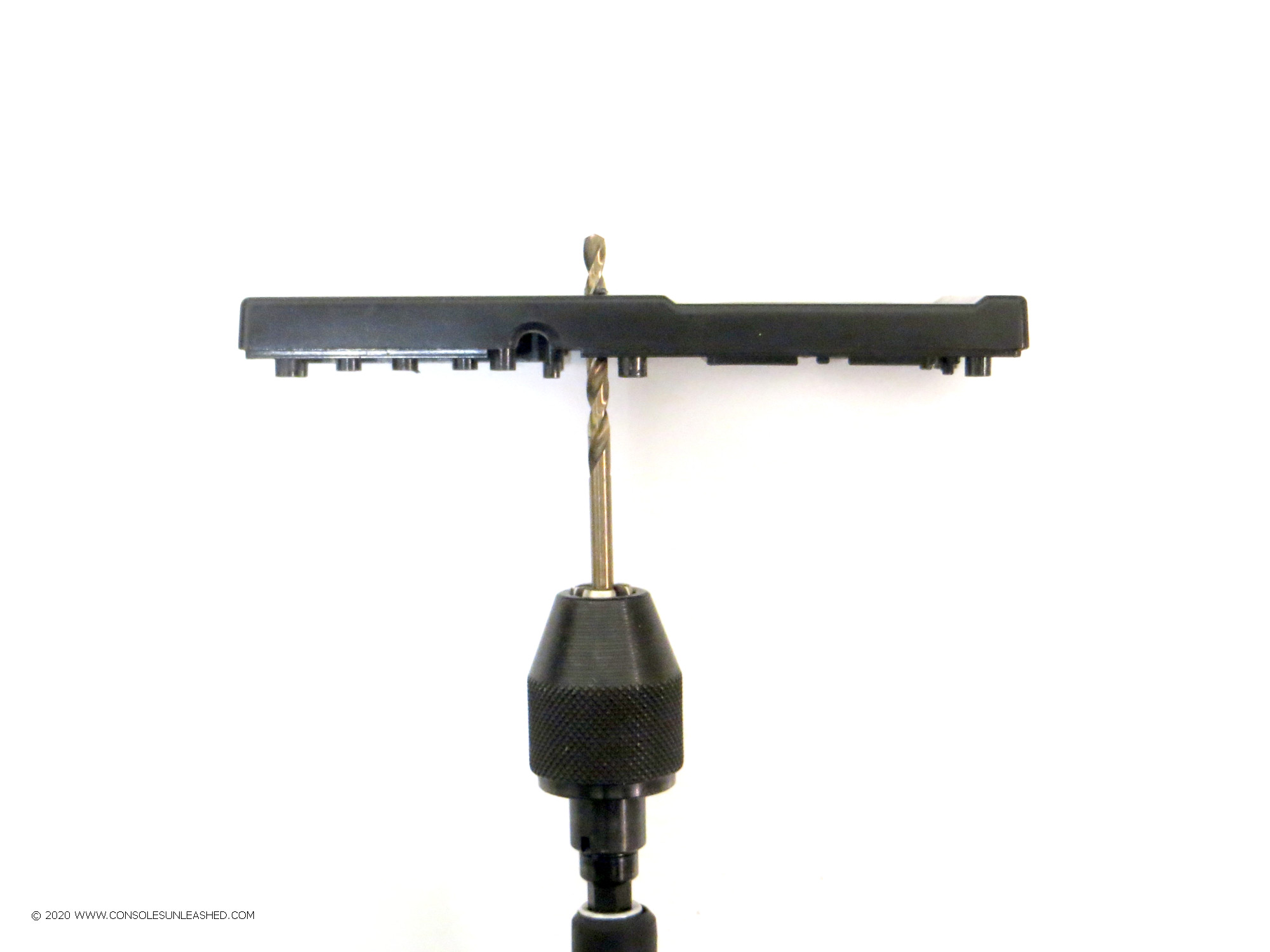
4 – Using a 3.5mm HSS twist drill bit, hand drill the hole using the template provided on the switch board. The drill will occasionally bite the PCB but this should not be a problem and just means the drill bit needs to be straighter.
A good quality drill bit will make easy work of the plastic.
5 – Remove the switchboard from the pegs. To remove the switch board lift each side only a small fraction at a time. Going too fast or lifting one end up too much will make the switch board get stuck or potentially snap the peg. Be gentle, it does come off but needs to be lifted relatively straight.
6 – Smooth out the drill hole if necessary with sand paper or file. If the switch bites or doesn’t press & return once finished, the hole needs to be slightly enlarged.
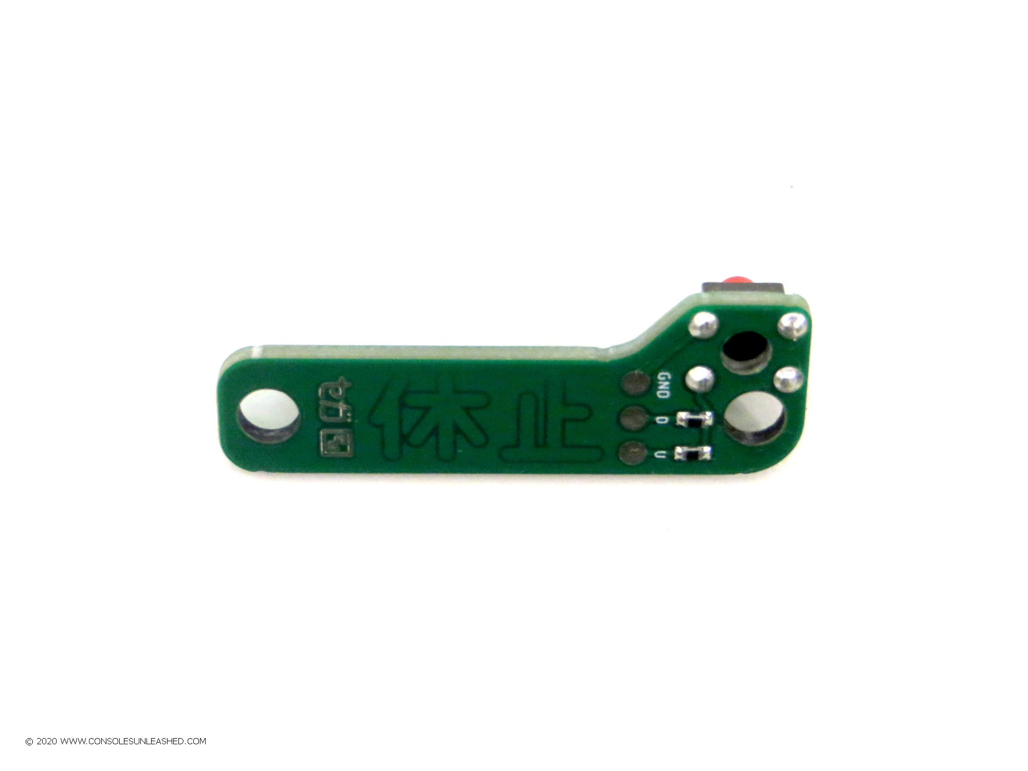
7 – Solder the switch into the switch board. Make sure to solder the switch on the correct side of the PCB. Notice the white lines designating the switch footprint. Trim the switch pins once soldered.
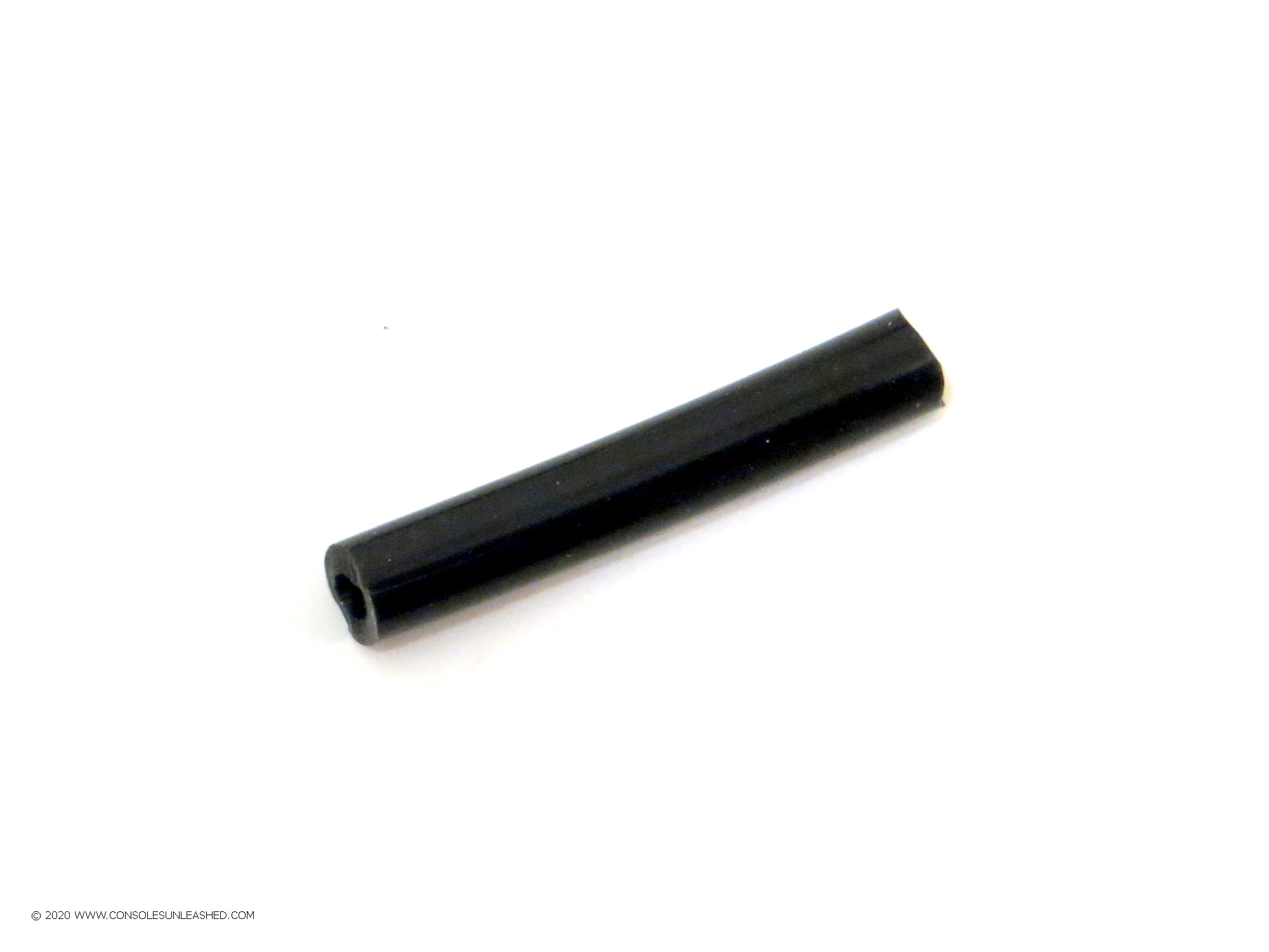
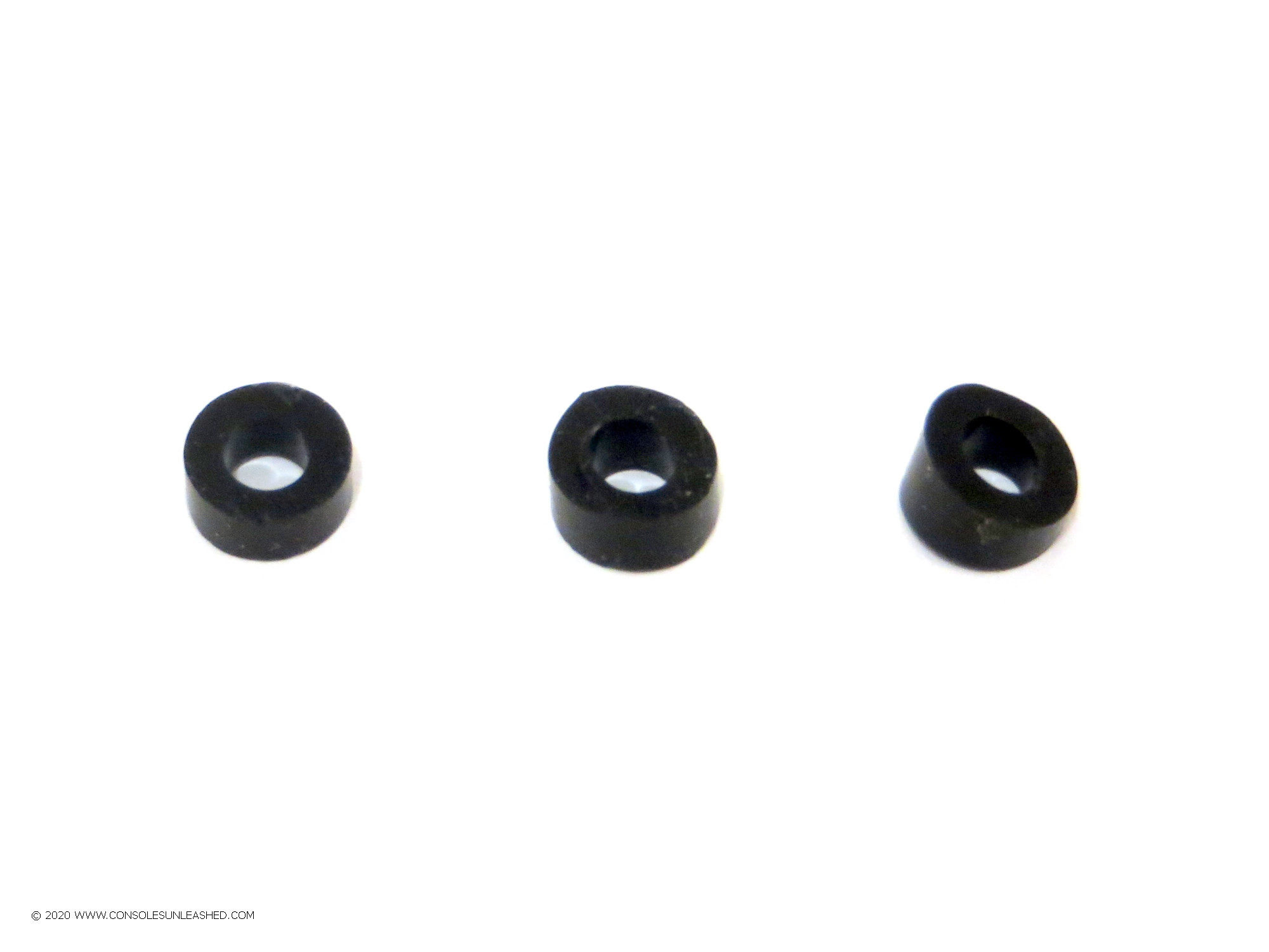
8 – Next step is to make the rubber spacers to hold the switch board PCB in place. Three spacers are needed. One to go below the PCB over the lower peg, and two to go above the PCB on each peg. Cut three small pieces from the 6cm silicone tube. Make one piece angled and around 4mm to 5mm to fit into the shaped plastic near the lower peg. The other two should be straight and around 5mm to 6mm.
To cut, use a sharp scalpel and slowly saw back and fourth to minimise downward pressure that will distort the shape of the silicone tube.
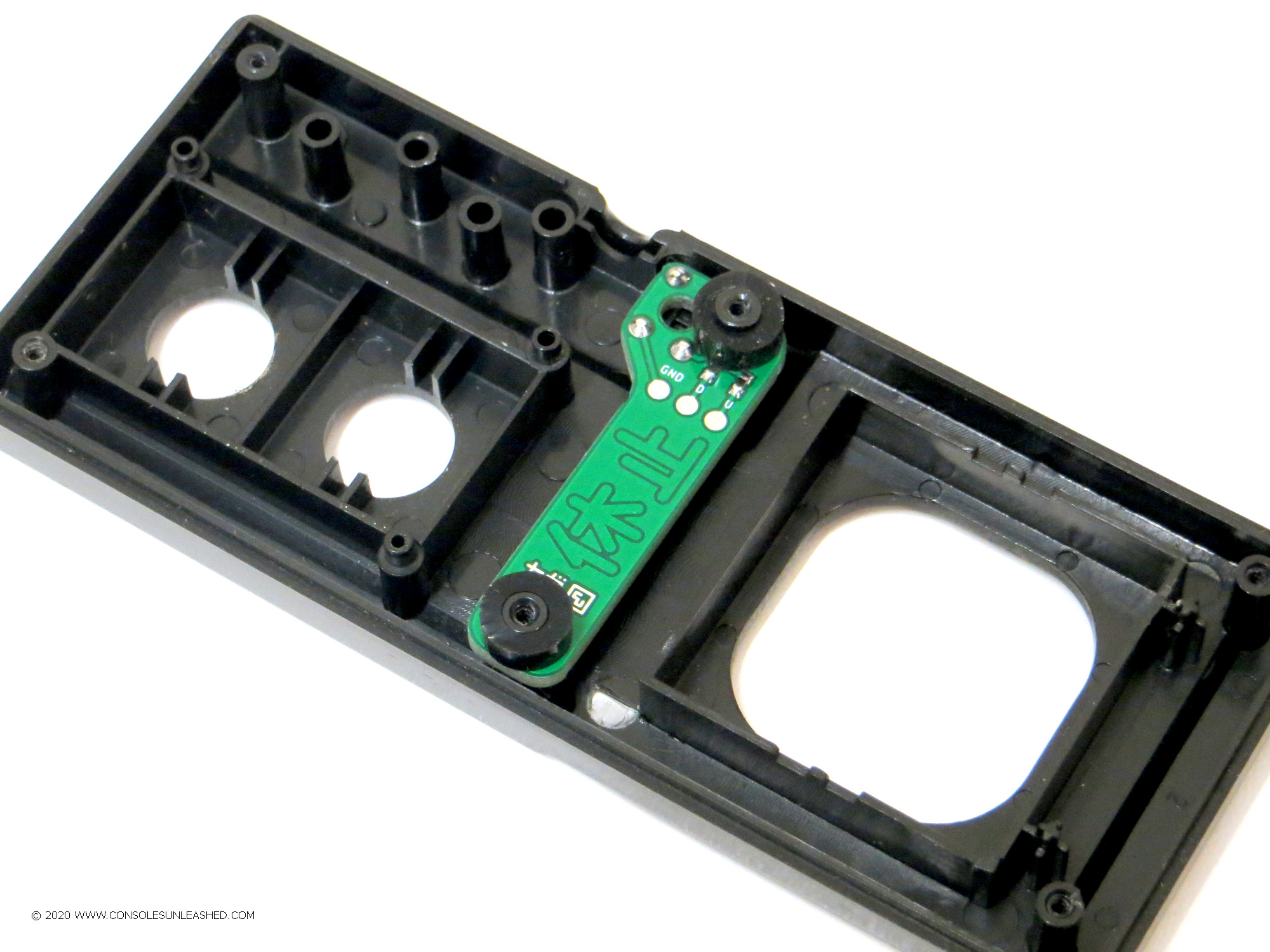
9 – Next step is to fit the spacers and switch board. Add the angled spacer to the lower peg, then the switchboard on top of this, making sure the switch fits into the drilled hole, then add the remaining two spacers on top of the switch board.
The switchboard should be straight and the spacers should reach to the top of the pegs. They don’t have to be perfect.
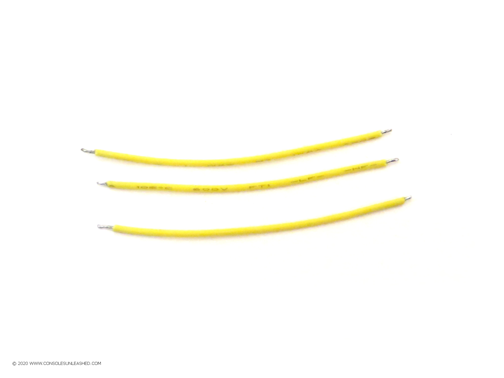
10 – Cut three 4cm lengths of 28awg stranded wire. Strip and tin them.
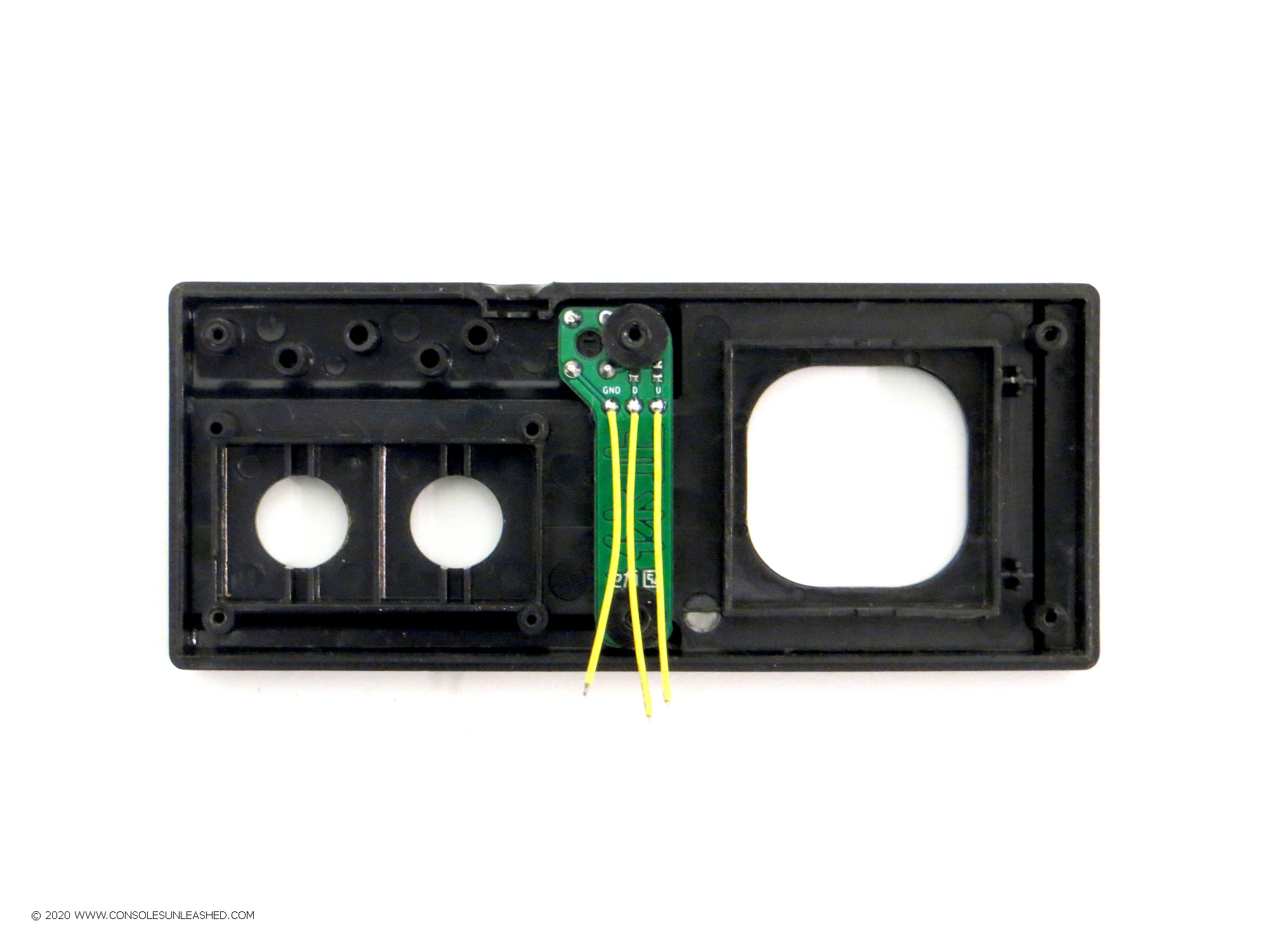
11 – Solder the wires to the three pads on the switch board.
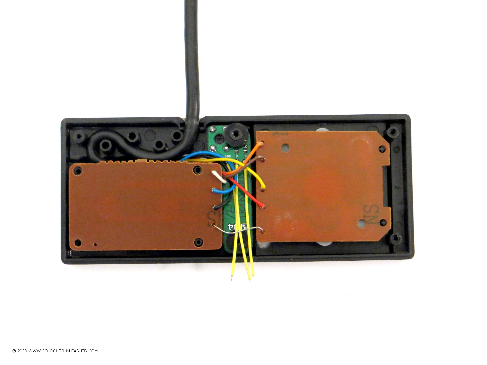
12 – Replace the parts of the controller and controller PCB.
13 – Lift up only the D-Pad side of the PCB and fold it back over the buttons half of the PCB. Solder the three switch board wires to the Up, Down and Ground solder points on the D-Pad PCB.
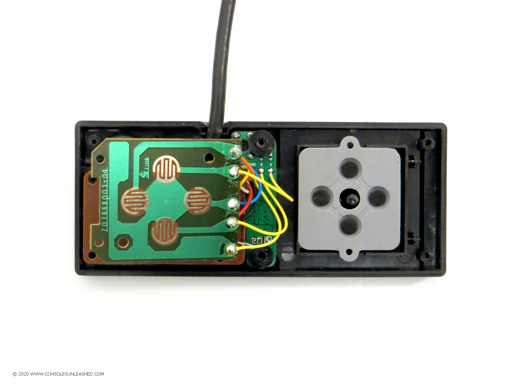
14 – When done, lay the D-Pad PCB back down and close up the controller housing.