This guide will show you how to change a Sega Master System model 2 from a PAL console to an NTSC console. This will make the console run in 60Hz video refresh rate and give colour over composite and RF video.
The purpose of this mod is to allow colour over RF and composite video for TVs that don’t support PAL. PAL Master System 2 consoles will work in PAL60 when doing a simple region mod to display 60Hz video. Depending on your TV this might result in a black and white image. Converting the console to work in NTSC will fix this, however the console will now display in black and white on TVs that don’t support NTSC.
There is currently no way of switching the Master System 2 between PAL and NTSC. A switchless region mod will change the console between 50Hz and 60Hz, but the colour encoding is always fixed.
Solder Maps
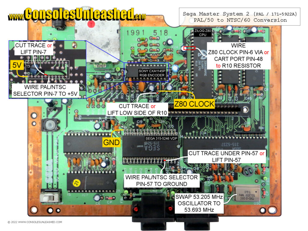
Sega Master System 2 – PAL / 171-5922A

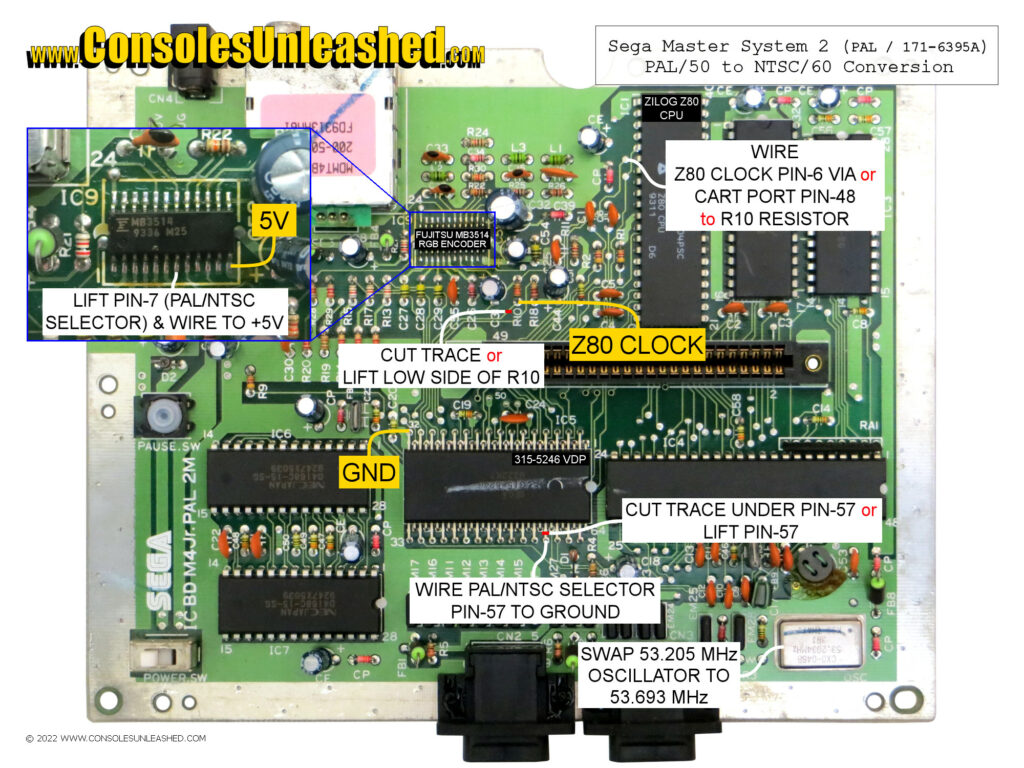
Sega Master System 2 – PAL / 171-6395A

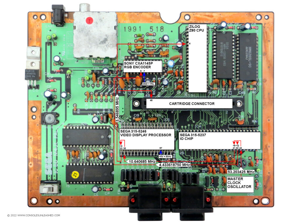
Clock Circuit
Sega Master System 2 – PAL / 171-5922A

Step-by-Step PAL to NTSC Conversion
Master Clock Oscillator
1 – Replace the PAL master clock oscillator (OSC) with an NTSC oscillator
- 53.203425 MHz is the PAL master clock frequency
- 53.693175 MHz is the NTSC master clock frequency
Sega 315-5246 Video Display Processor
2 – Change the operating mode from PAL to NTSC.
Pin 57 is the PAL/NTSC Selector pin.
- Ground = 60Hz
- +5V = 50Hz
Change this from the +5V connection to a Ground connection. This can be done by either lifting the pin or cutting the trace that runs underneath it. Then wire it to the ground pin.
Sony CXA1145P / Fujitsu MB3514 RGB Encoder
3 – Change the operating mode from PAL to NTSC.
Pin 7 is the PAL/NTSC selector pin.
- Ground = PAL
- +5V = NTSC
Change this from the Ground connection to a +5V connection. This can be done by either lifting the pin or cutting the trace that runs to it on the underside of the board. Then wire it to the +5V pin.
4 – Break the subcarrier clock input to the RGB Encoder
Pin 6 is the subcarrier clock input pin. Lift the lower side of the R10 resistor or cut the trace that runs to the lower side of the resistor.
- PAL Subcarrier = 4.433618750 MHz
- NTSC Subcarrier =
Zilog Z80 Central Processing Unit
5 – Wire the Z80 clock to the RGB encoder
The Z80 clock can be taken from either the small via in front of Z80 Pin 6 or Cartridge Port Pin 48.
Add a wire from either point to the lower side of the R10 resistor. If the resistor was lifted or the trace was cut, the connection needs to be made to the lower side of the resistor regardless.