This guide will show you how to install a switchless region mod into a Sega Master System 1. It will use the pause button to change the video rate of the console between 50Hz and 60Hz.
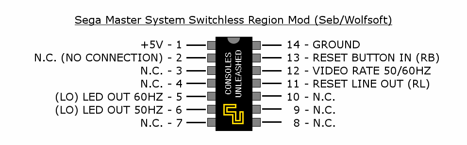
Mod Pinout
Solder Maps
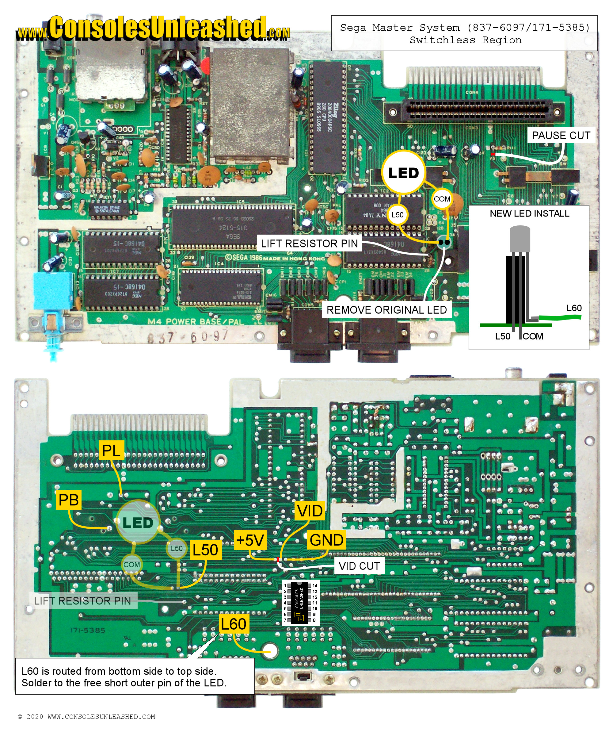
Sega Master System – 837-6097 / 171-5385 / PAL
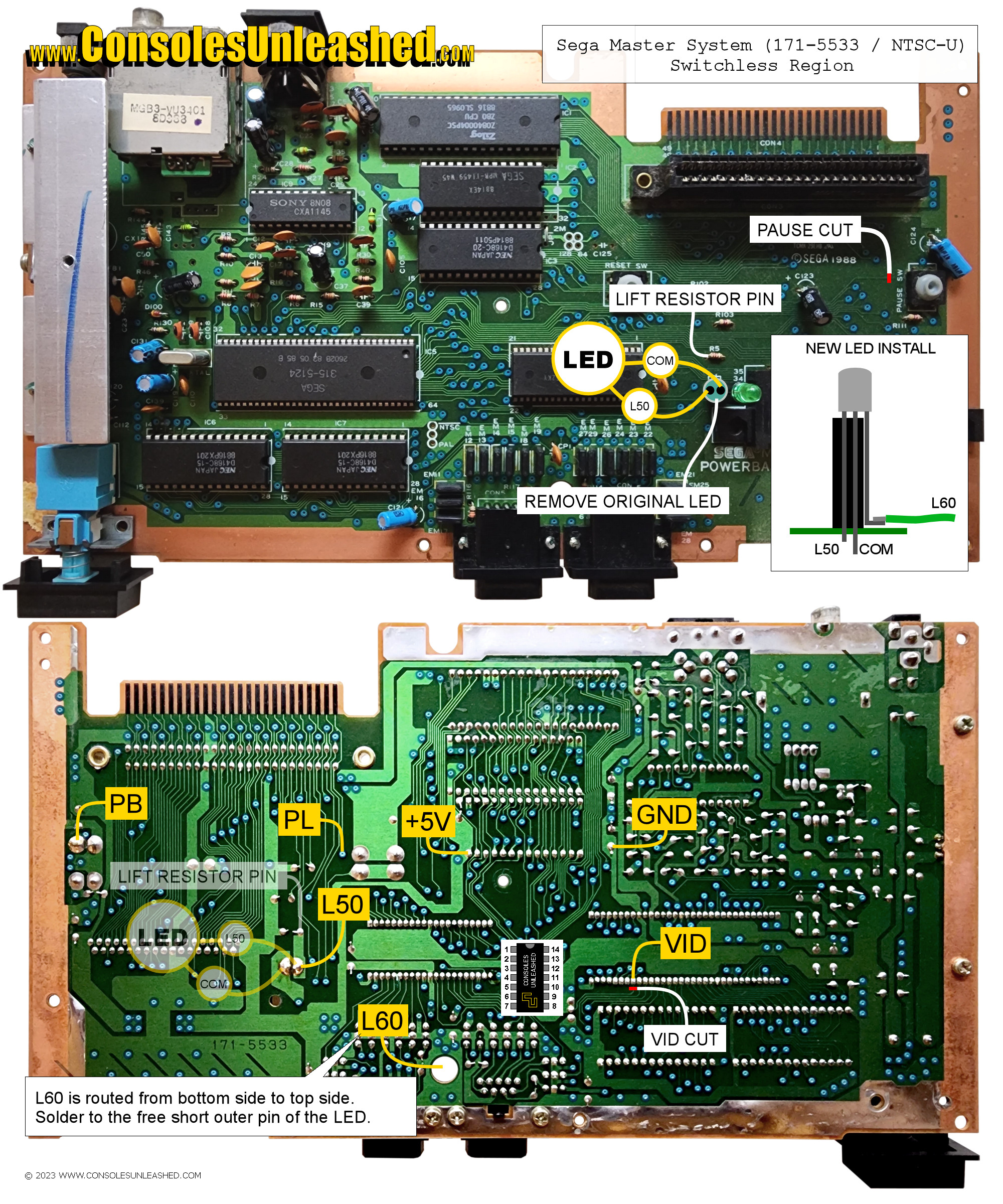
Sega Master System – 171-5533 / NTSC-U
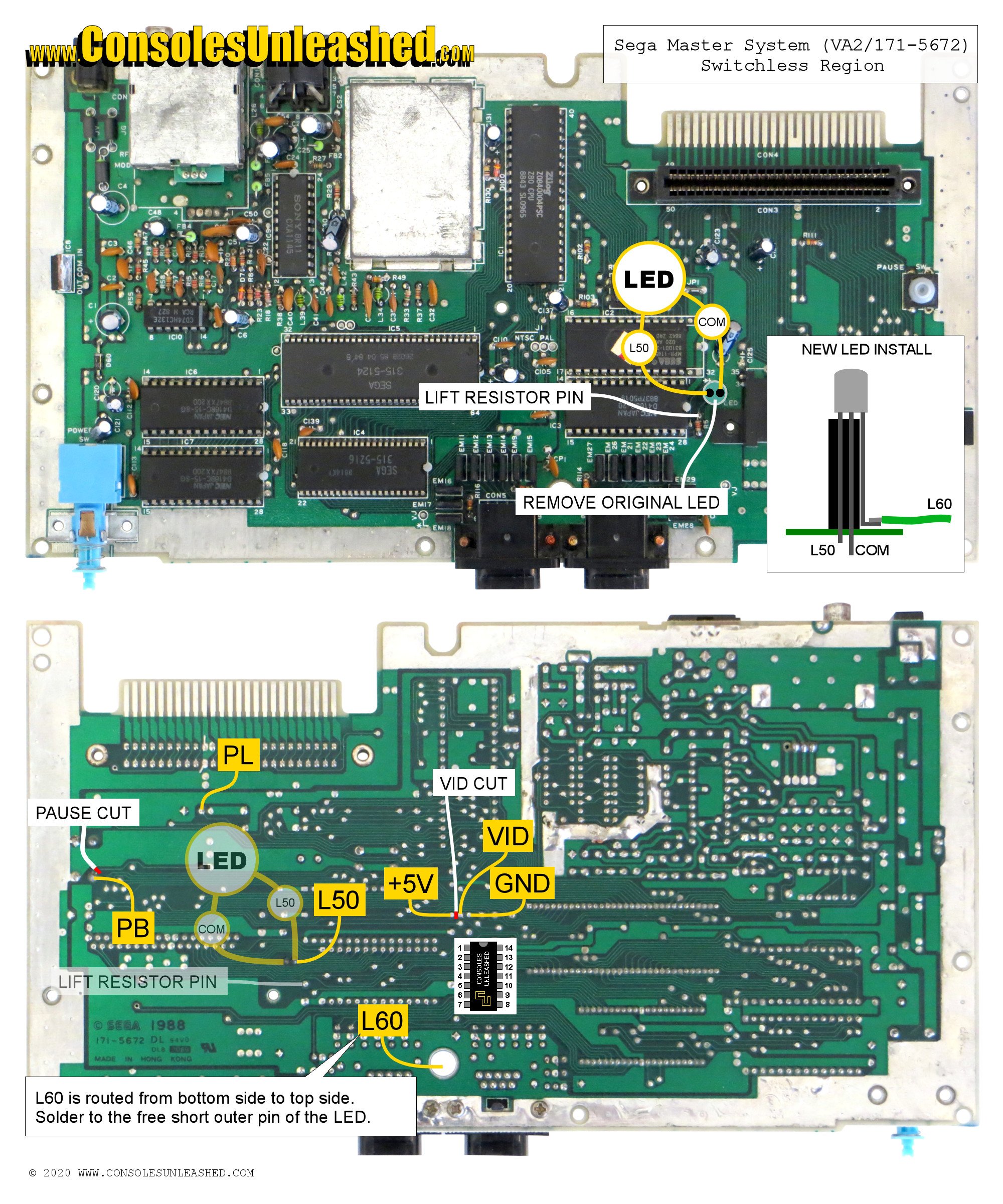
Sega Master System – 171-5672 / PAL / VA2
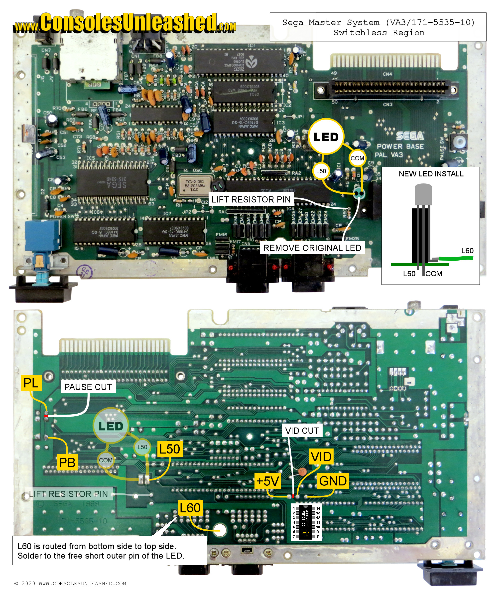
Sega Master System – 171-5535-10 / PAL / VA3
LED Installation
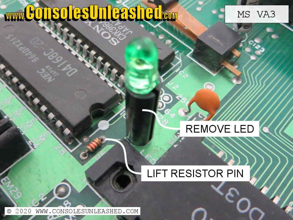
1 – Remove the LED from top side of the board
2 – Lift one side of the resistor that is coming from the original LED, labelled R5 (VA1) or R50 (VA3). This will disconnect the LED pads from the Master System board and allow the new LED to be controlled by the modchip. Lifting the resistor pin is non-destructive but the trace can also be cut.
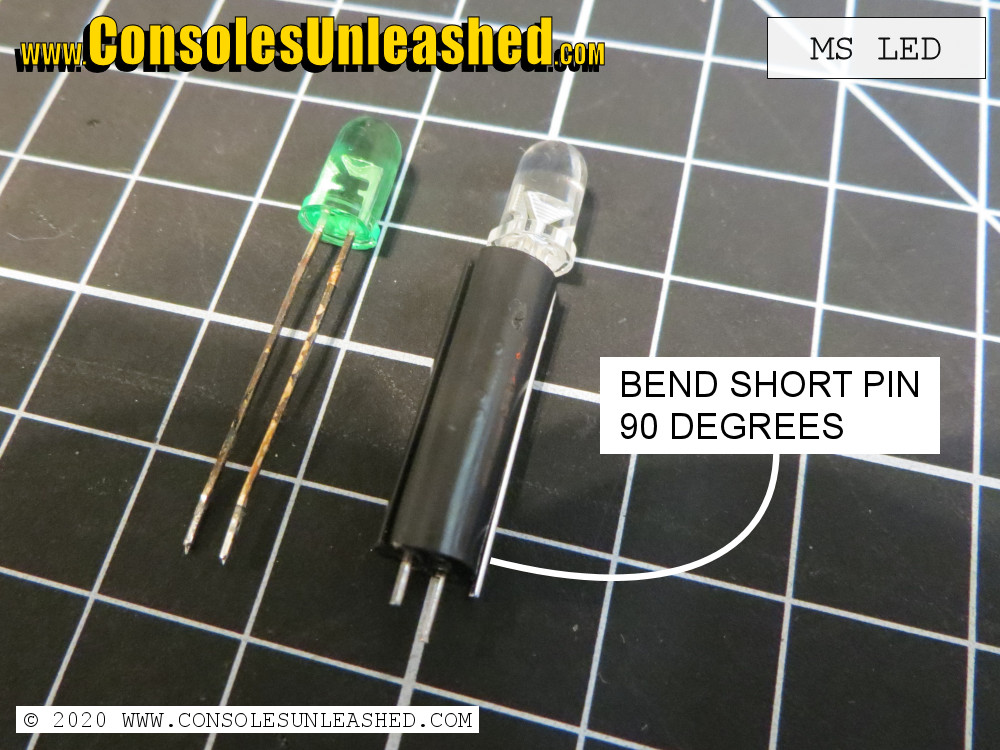
3 – Insert the new LED into the original plastic LED sleeve that was removed from the board. Leave the Short Outer lead (green) of the LED as the free lead.
4 – Put a 90 degree outwards bend in this short outer lead that is just slightly higher than the bottom of the plastic LED sleeve.
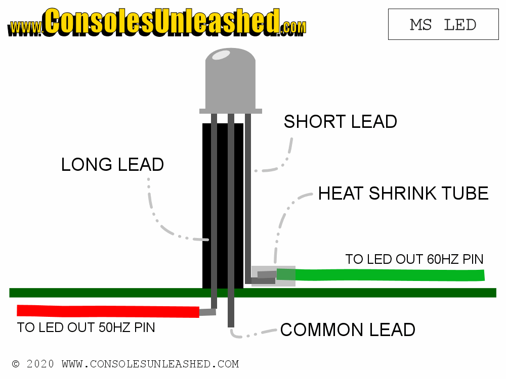
5 – Solder a wire to the bent lead. It will be more difficult once the LED has been soldered in place. The lead/wire connection can be covered with heatshrink tube but this is not necessary because there will be no movement once complete.
6 – Place the new LED into the original LED holes. The free Short Outer lead (green) will be towards the Master System card slot on the right.
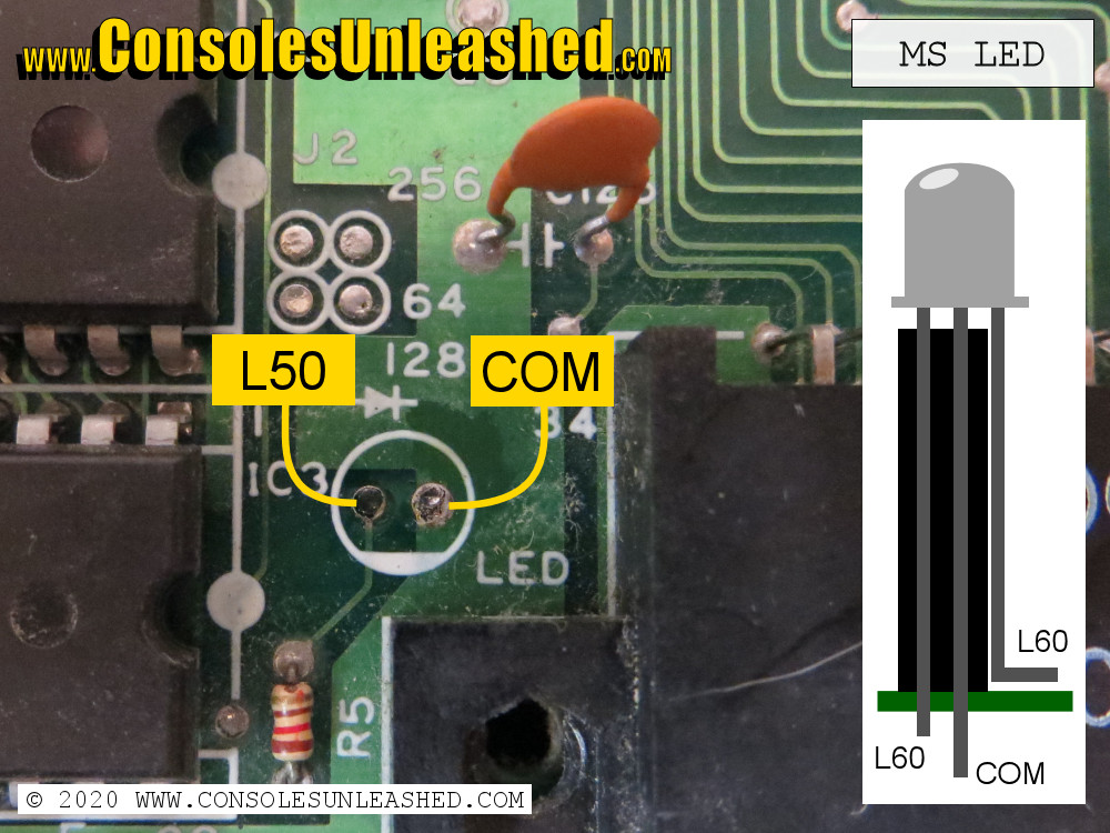
7 – Solder the new LED in on the bottom side of the board.
8 – The wire that runs from the short outer lead of the LED must be wired through the hole to the bottom side of the motherboard and soldered to pin 5 of the modchip.
9 – Wire pin 6 to the LED pad, this will be the long outer lead of the LED.