This is installation guide covers installing a switchless region mod into a Sega Mega Drive. It can be used for any chip code and all Mega Drive switchless region mod-board variations that might be encountered when doing this mod. This guide currently includes the Mega Drive revisions PAL VA4 & PAL VA5/VA6. It should be possible to mod any other revision based on these two board revisions.
This mod will make the Sega Mega Drive multi-region, allow games to run in 60Hz, and display their original Japanese language & titles of compatible games. Upgraded versions include the ability to change region and reset using the controller pad, switch a Mega CD MultiBIOS, and change the master clock frequency to match the region.


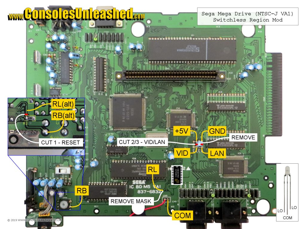
Solder Maps
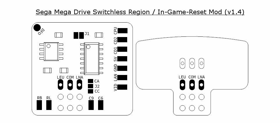
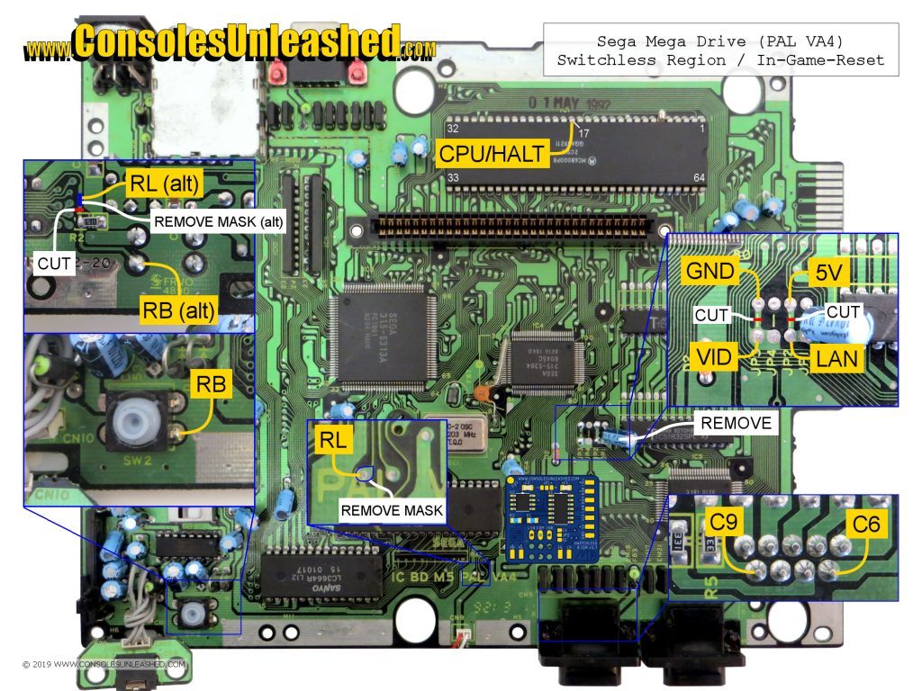
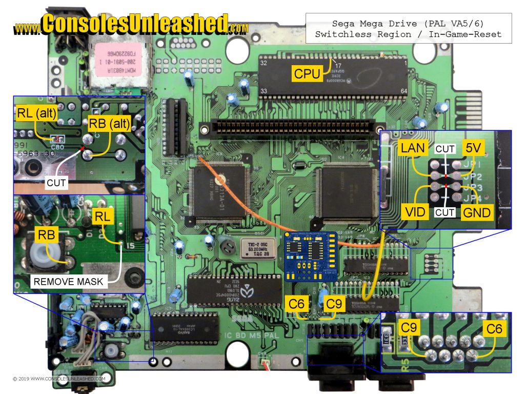
Depending on what code or mod-board is being used, not all connections shown in this guide will be applicable. Only connect what is shown in the pinout for the particular code used or what is labelled on the mod-board solder pads. Ignore all other connections.
Sega Mega Drive – NTSC-J / 837-6832 / 171-5742 / VA1
Sega Mega Drive – PAL / 171-5872-20 / IC BD M5 PAL / VA4
Sega Mega Drive – PAL / 171-5963-30 / IC BD M5 PAL / VA6
Language & Video / Power & Ground
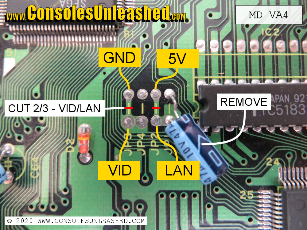
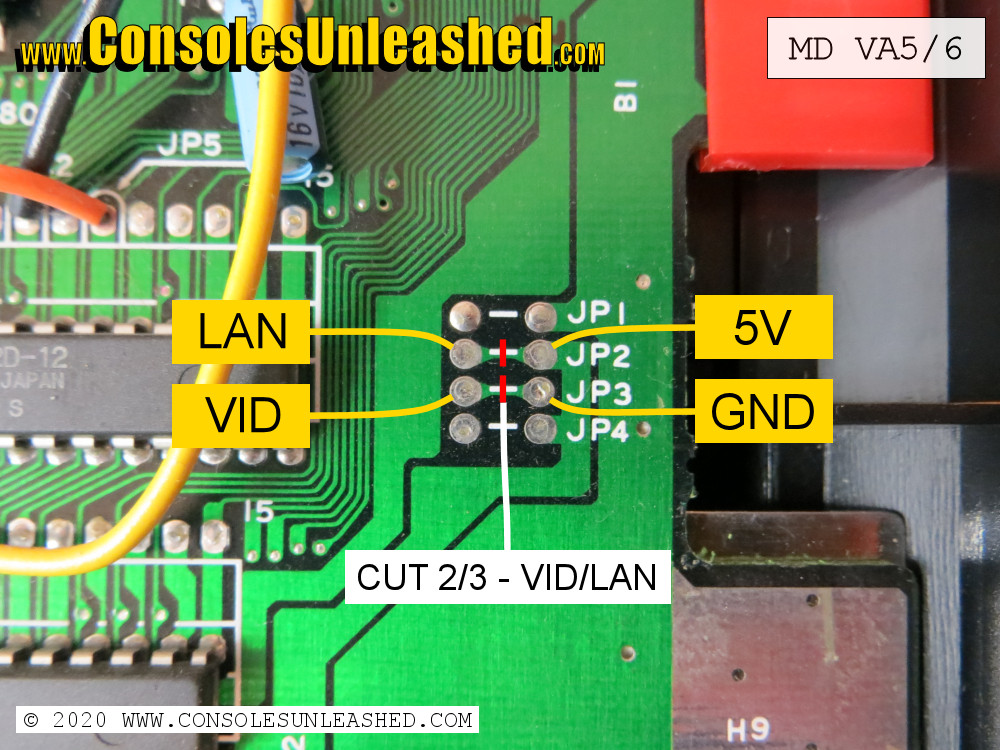
The language and video rate jumper settings on the mainboard are what determine the region of the Sega Mega Drive console. These jumper settings are easily overridden by cutting the connections and then supplying +5V or Grounding in varying ways.
| JP1-2 (Language) | JP3-4 (Video Rate) | |
| 50Hz/EN (Europe) | +5v | Ground |
| 60Hz/JP (Japan) | Ground | +5v |
| 60Hz/EN (North America) | +5v | +5v |
There are three different arrangements of jumpers in the Mega Drive. VA0 to VA4 which are horizontal and not sequential, then VA5 which is vertical and sequential from bottom to top, then there is VA6 which is vertical and sequential from top to bottom.
(IMAGE OF JUMPERS HERE) (IMAGE OF REGION SETTINGS HERE)
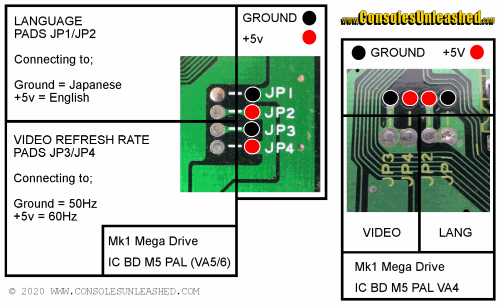
1 – Cut the traces between the power/ground side and video/language side of the jumpers (red lines on images).
2 – Solder LAN and VID (Before 5V and GND)
3 – Solder 5V and GND.
Reset Button
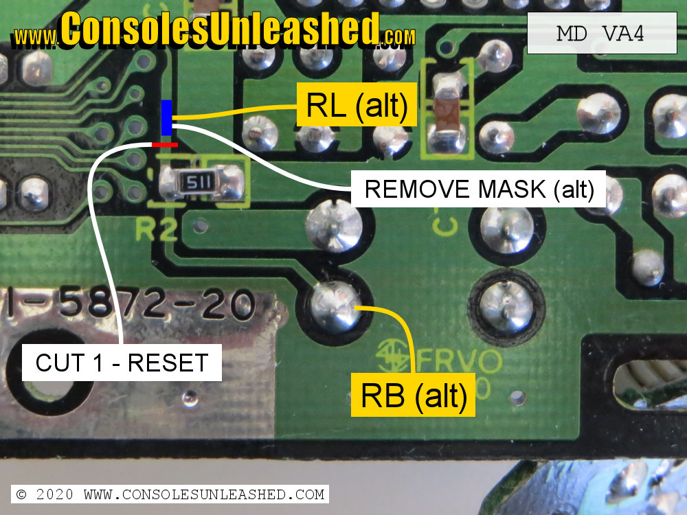
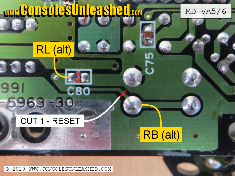
For the PIC chip to control the regions of the Mega Drive it needs to take the signal from the reset button and then rout it accordingly. This is done by cutting the line going from the reset button and putting the PIC chip in this path. The PIC chip will then determine how the reset button is pressed and then send out any required signal. A quick press of the reset button will mean the PIC chip will send out a normal reset as if the reset button line was not cut. If the reset button is held, the PIC chip will send out signals to change the region and language and not send out a normal reset signal.
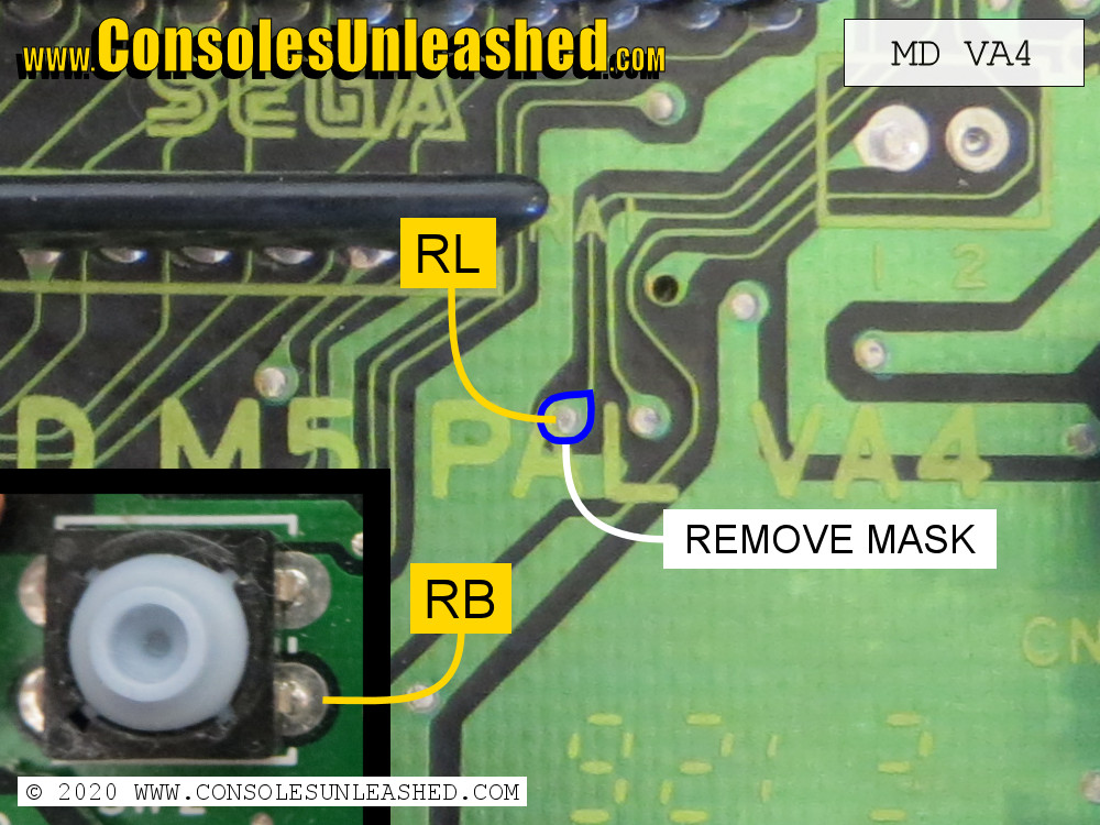
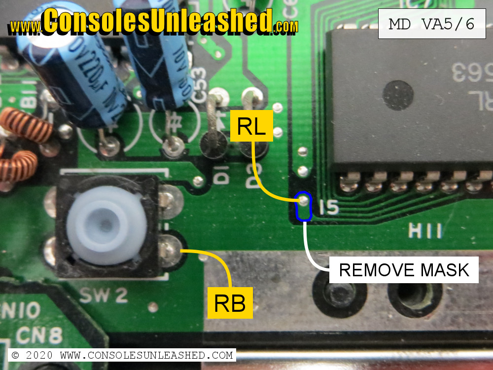
1 – Cut the reset button trace on the underside of the motherboard (red line on images).
2 – Solder RB to the reset button pin.
3 – For RL, solder will need removing from the vias before soldering (blue circles in images). Scrape away the green solder mask from the small pad to reveal the copper underneath. Solder RL to this. For best results use the tip of a scalpel and view under magnification. The area should be shiny before soldering.
Controller Port
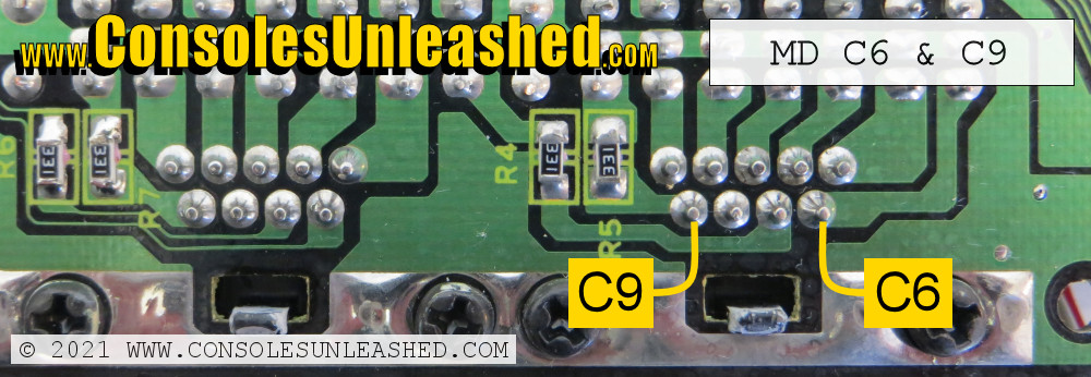
Connect C9 and C6 to their corresponding controller port pins.
- Controller port pin 6 is A + B
- Controller Port pin 9 is C + Start
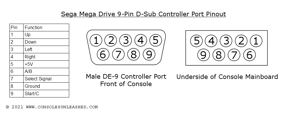
You can place the wires through the controller connector from the top side of the mainboard and pull it through with some tweezers. This is the cleanest method and much more preferable to routing the wires around the outer side of the mainboard which can result in crushed wires and possible shorting.
CPU Halt (CPU)
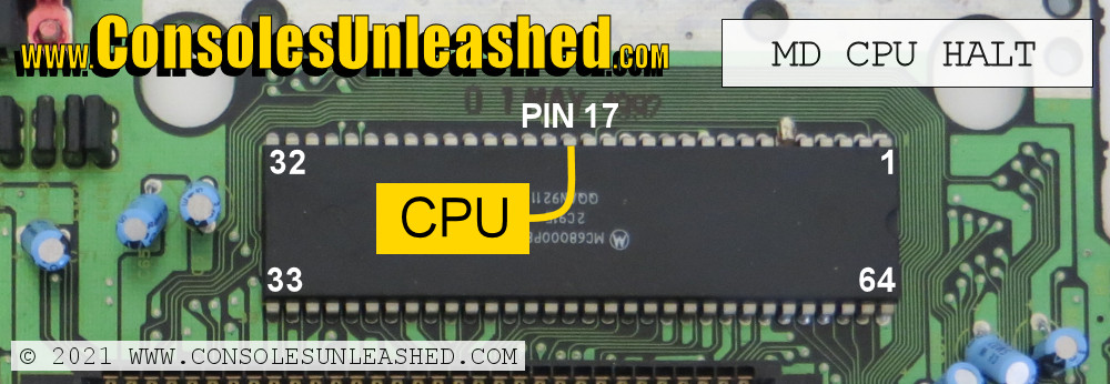
Connect the CPU pad to Pin 17 of the CPU.
When this is connected the game will pause when START+A+B+C is held long enough to start cycling through the console’s regions. Only connect this if you want the game to pause when cycling through the regions.
LED Installation
This is the most difficult part of a Mega Drive switchless mod install but it is entirely optional. Without it though, the region of the Mega Drive will be difficult to determine.
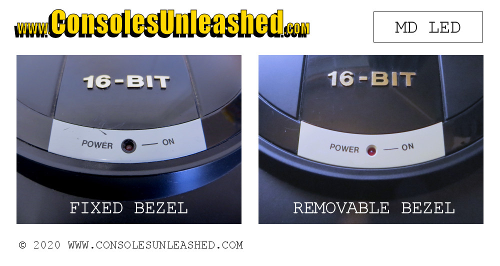
Two Types of Top Case LED Fixtures
Removable Bezel and LED
This is the easiest LED to remove because the bezel cover that is holding in the LED can be unclipped. The LED will then come straight out.
Fixed Bezel and Sealed in LED
This is more difficult because the LED will need cutting out from the underside of the top case. The metal legs of the LED will be in the way when cutting the hole. Once the hole is large enough, the LED can be removed.
Removing the Old LED
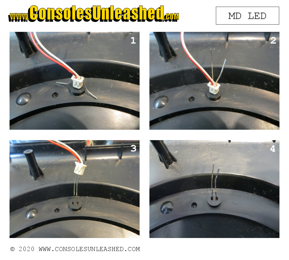
Remove the wires connecting the motherboard to the top cover. Removing from the top cover requires bending the metal legs of the LED up and then pulling the plastic connector off. The connection to the motherboard will require desoldering.
Cutting the Hole
Side cutters, a hand drill or an electrical rotary tool can be used to cut the hole for the new LED. Then a file can be used to smooth the edges for a neater appearance. Slow and steady is the only way to do this without making a mess. Start in the center and work outwards and do not go too deep to avoid cutting into the bezel.
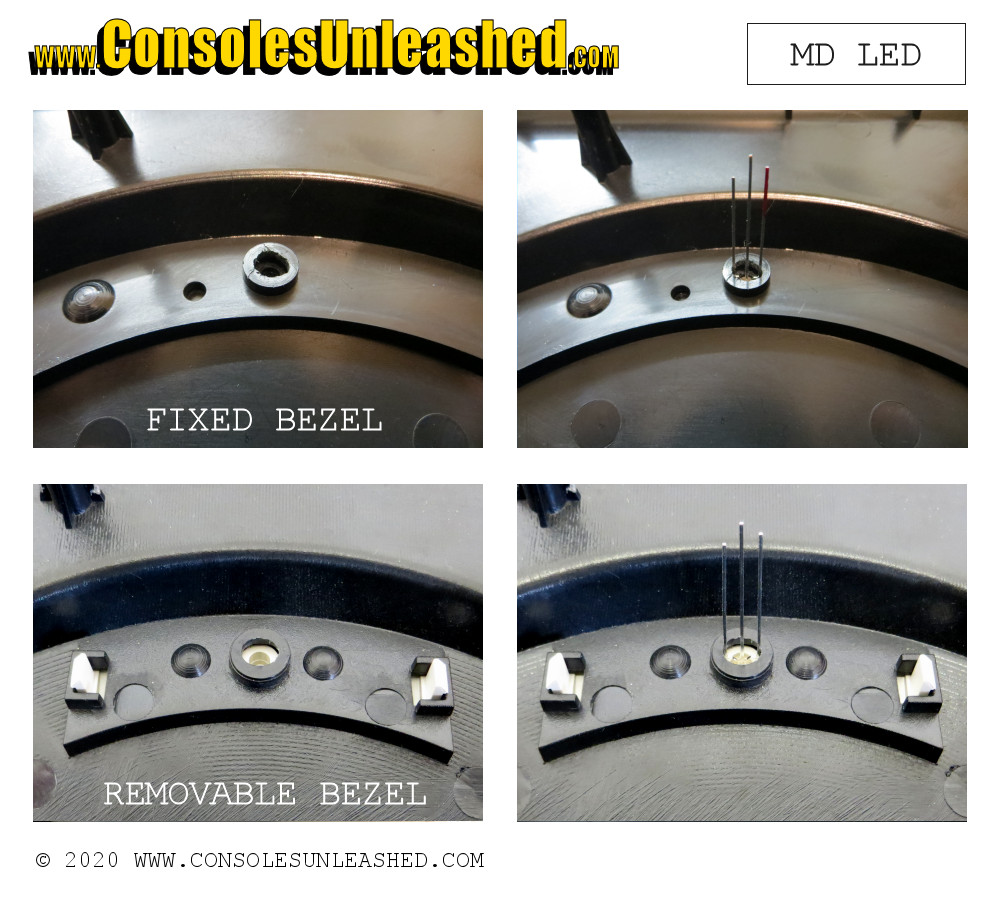
The hole should be just wide enough so the new LED fits.
LED holes for removable bezel shells can be made much smaller than holes in fixed bezel shells. On a removable bezel shell, remove the bezel and remove the LED, then carefully cut the middle from the original LED holes to make a rectangle. It might need widening slightly. This will make the LED cut on removable bezel shells much cleaner.
Wiring the LED (Deadbug Kits)
Cut back the LED legs to the little nodules then solder wires from the Chip to the LED. How you wire the LED is entirely dependent on what type of LED you have.
An example of using Borti4938 code with a common cathode LED that has red on the long outer lead and green on the short outer lead.
- Chip Pin 5 (LO/50) > Resistor > Short outer lead of LED
- Chip Pin 6 (LO/60) > Resistor > Long outer lead of LED
- Chip Pin 7 (SET LED TYPE) > Ground point on board (COM) > Middle lead of LED.*
*Chip Pin 7 (SET LED TYPE) and the middle lead of the LED will need connecting to a +5V source if using a common anode LED.
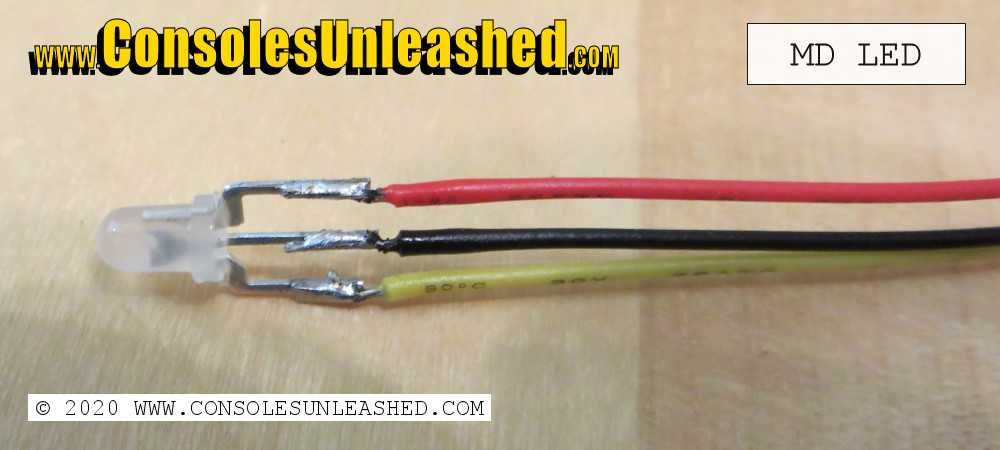
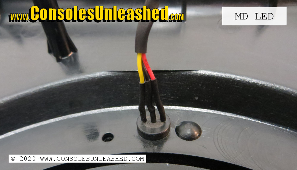
Heat shrink tubing can be put over the individual wire solder connections for better appearance and strain relief, then a further larger piece of heat-shrink over all the wires to keep them together. Do not over do this though as the wire needs to be quite flexible in order to fold under the case top.
Once the LED and wires are soldered, the LED will need fixing into the case hole. There are a number of ways to do this.
Hot Glue – Whilst hot glue will not be very aesthetic, it is easy to apply and can be removed with relative ease if the mod ever needs changing.
Milliput – This is much more difficult to do well and more permanent. The milliput can be carefully pushed into the hole and round the LED leads to create an almost seamless surface, but it requires 24 hours to set and it is very difficult to do neatly.
Wiring the LED (Consoles Unleashed LED Board)
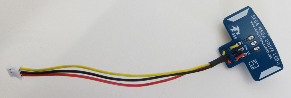
Custom PCB mod kits will come with a pre-wired female JST connector and a separate LED board with pre-wired male JST connector. Whilst this system was designed to be as easy to install as possible, it still require the permanent modification to the top shell of the Mega Drive.
Fixing the LED
1 – Place the LED into the hole. Check the top side of the case to see how far out the LED sits. If it is too far, a piece of tape over the hole on the top will ensure the LED is positioned correctly.
2 – Remove backing from the adhesive pads of the LED board.
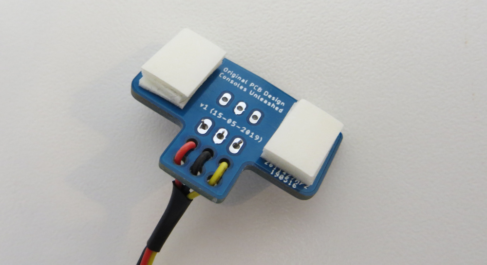
3 – Place the LED board over the LED and press down firmly. My kits will come with LEDs that have Red as the long outer lead. Make sure this long outer lead is placed into L60. Short outer lead will be L50. This will ensure that Red is used for the North American region.
If there are circular lumps at either side of the LED hole, these can be removed with side cutters so the LED board sticks down better.
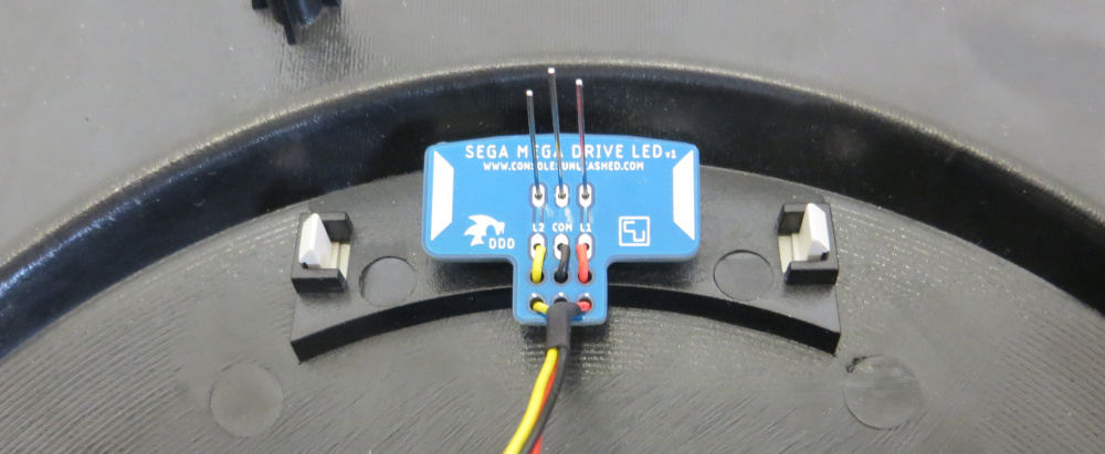
4 – Solder the LED in place. Make sure to only solder the LED when the sponge adhesive pad has fully recovered from being pressed down.
Note that the adhesive pads can be removed and the board can also be fixed in place with hotglue. This will give the LED more stability, but the adhesive pads will be strong enough to keep the LED in place and are easy to replace if there are any problems, but there may be some movement of the LED. Do not solder the LED whilst the foam tape is compressed in any way otherwise the LED will be sunk into the bezel hole too much.
Jumpers / Special Pins (J1, J2)
Depending on the board revision or code used, these jumpers & special pins might not be available.
J1 / Pin 4 (Borti4938 Code) – Reset On Mode Change – When set to (+) or a +5V source, changing the region via the reset button or controller will have an instant affect on the video rate. When set to (-) or ground, changing the region via the reset button or the controller will reset the console and the new region will be set on boot up.
J2 / Pin 7 (Borti4938 Code) – Set LED Type – When set to CA or a +5V source, a Common Anode LED should be used. When set to CC or Ground, a Common Cathode LED should be used.
Program Your Own
If you want to make this yourself you can get the codes from the following links.
D’force3000 (D4S)
- Official web page with the download http://www.dforce3000.de/?uid=12
- Wayback machine https://web.archive.org/web/20191201071610/http://www.dforce3000.de/?uid=12
Borti4938
- Borti4938’s Mega Drive switchless mod project page at GitHub https://github.com/borti4938/Switchless_SEGA_MasterSystem_MegaDrive/tree/master/MD_Switchless
