Work in Progress. Will contain errors.
The state of Super Nintendo mod guides across the internet is poor to say the least. What currently exists is mostly incomplete and confusing and does not give the reader a complete picture of the process.
I want to create a thorough and complete guide to region modding the Super Nintendo with full mainboard maps of solder points for each console revision. Starting from the installation of just a simple SuperCIC, then SuperCIC with uIGR, then adding region patching, to finally the larger all in one boards from Borti4938 that contain Dual Frequency Oscillators and DeJitter mods. All whilst keeping a clear distinction to what aspect of the mod guide pertains to which part of the mod.
I might need some help with this. I need clean board photos of all revisions at least 4000px by 3000px, front and back and then possibly a little help with the idiosyncrasies of each board revision. If not, I will get there on my own but this might take a while.
Mod Pinout

Pin 13 Reset In also needs connecting to ground via a 10kOhm resistor.
Pin 3 D4 Out can be ignored if a D4 patch is not used.
Pin 4 Region Timeout must be connected to +5V if a D4 patch is not used.
More details soon.
Solder Map
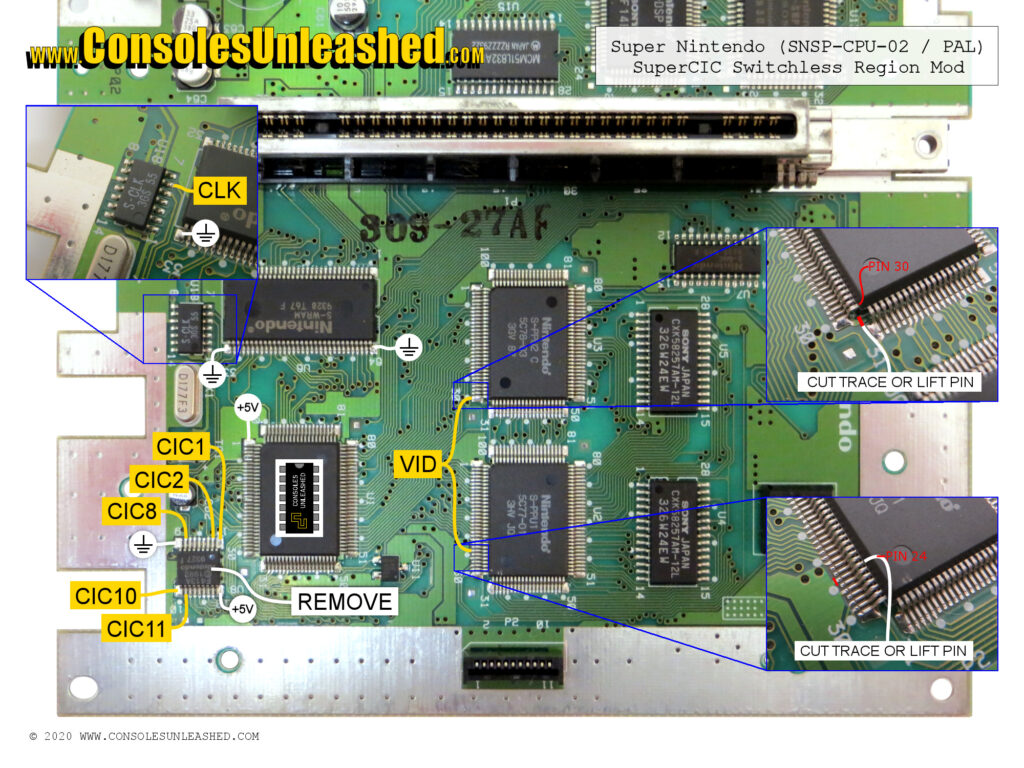
Super Nintendo PAL / SNSP-CPU-02
Super Famicom NTSC-J / SNS-CPU-RGB-01
May contain errors.
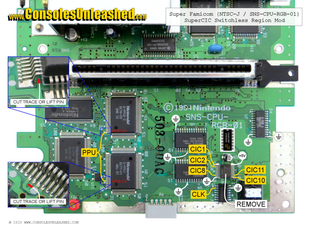
CIC Lockout Chip Connections
CIC solder points should be common with all Super Nintendo revisions.
Coming soon.
Cartridge Port Connections
Cart pin solder points should be common with all Super Nintendo revisions.
Pin 55, Pin 24, Pin 25 all have continuity with the relevant CIC pad. Pin 56 does not have continuity with CIC pad 7, but should be an alternative point.
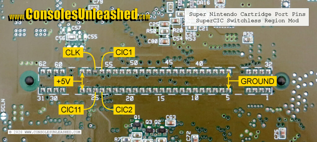
Clock In / CIC7
Solder locations may differ between revisions.
More details soon.
PPU
These PPU solder points should be universal to all multichip Super Nintendo revisions.
PPU1 Pin 24 and PPU2 Pin 30 are what determine the video rate of the Super Nintendo. These are both hard set to either a voltage supply or ground. Both pins need isolating from the Super Nintendo mainboard and then wiring to SuperCIC Pin 12.
Some revisions will allow the trace to be cut at PPU1 Pin 24, others will not because the trace will run underneath the PPU IC. Lifting is necessary in this circumstance. PPU2 Pin 30 trace that runs back and underneath the IC can be carefully cut, but lifting the pin is easy as it is an end pin.
More details soon.
Reset
Pin 13 Reset In (CIC 8) is the reset button pin. Solder to either CIC8 pad or the lower right reset button pin.
Pin 11 Reset Out (CIC10). Solder to CIC 10 pad.
More details soon.
Controller Board LED Install
In a switchless region mod, the LED functions as an indicator of the console’s region. The original LED will need removing from the controller port and a three pin dual colour LED installing in its place.
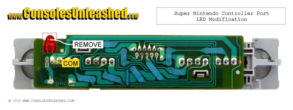
The LED is housed between the PCB and controller face plate. It is possible to remove the LED without dismantling the controller port. Use a solder pump or solder sucker to remove the solder from the two pins in the red box in the image above. If the solder is sufficiently removed, the LED can be bent forwards to pull the pins through the hole and out from between the PCB and face plate. If there is some solder left over, simply heat the pins whilst pulling the LED forward.
To secure the new LED, the central common pin will need to be soldered to the point marked COM on the image. The two outer pins of the LED will be left dangling down. Both these dangling pins will be wired up to the switchless region mod.
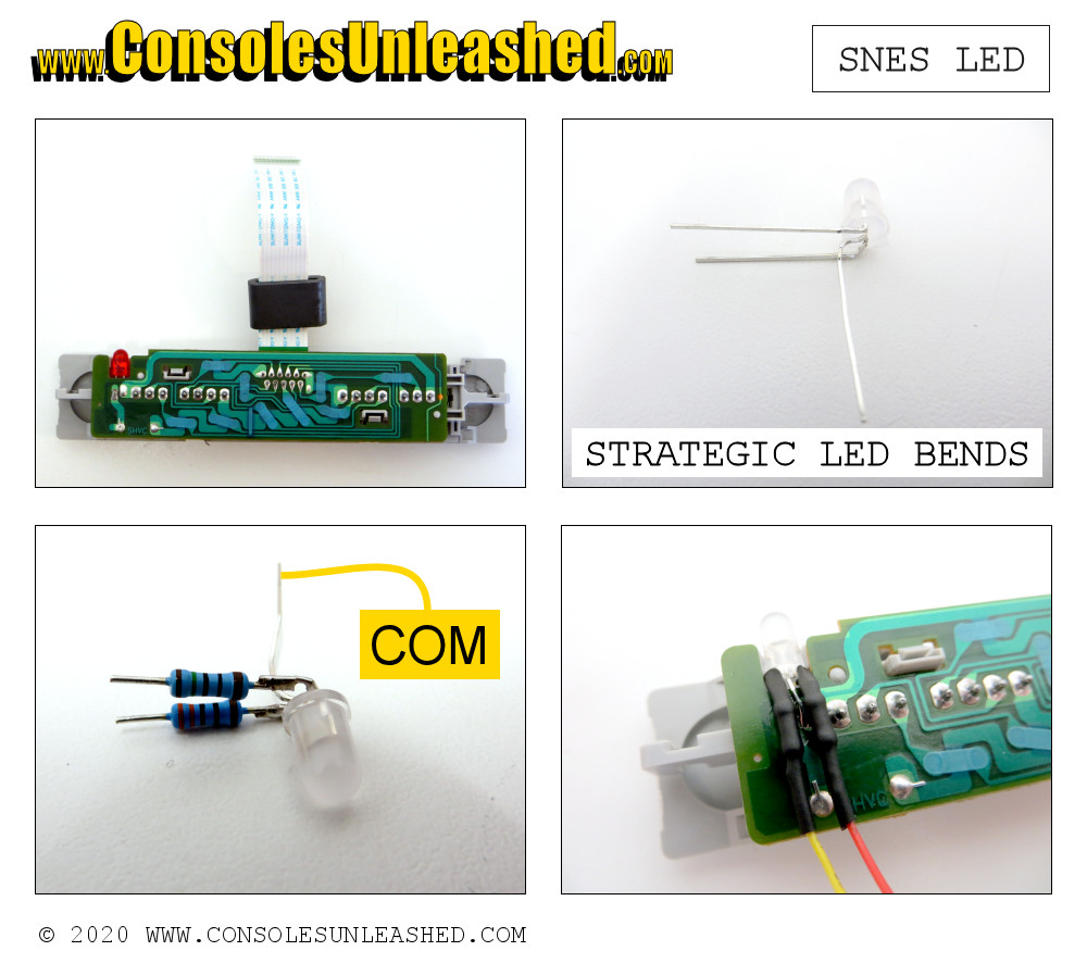
The new LED will need bending in a specific way in order to do a neat install. Make two bends in the middle LED pin, first by making a bend straight out, then another straight down at the outer edge of the LED base. Then bend the outer two pins straight out.
Solder the two resistors to the outer pins of the LED then solder the middle LED pin (COM), onto the hole of the controller port PCB marked COM.
Once the LED is secure, wire up the two outer pins of the LED and don’t forget to add heatshrink tubing to prevent the outer LED pins shorting with the middle LED pin, and to provide strain relief.
Once the LED is wired up, bend the two outer pins downwards so they are flush with the controller port PCB.
1-Chip Clock Circuit
In order for SuperCIC to work in a 1-chip Super Nintendo, the installation of a clock circuit is necessary.
Coming soon.
Adding uIGR (In-Game-Reset)

The in-game-reset add-on from Borti4938 allows the region and reset to be controlled with the controller. It requires connecting up to the SuperCIC and three controller port pins.
More details soon.
Region Patch
Coming soon.